


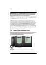

Voice over IP (VoIP) VoIP System Telephones
72
LAN Port: Allows the telephone to connected to the LAN. Use a non cross-over
RJ45 patch cable to connect to a Hub or Switch.
PC Port: Allows the telephone to be connected to a workstation computer. Use
a non cross-over RJ45 patch cable to connect to the PC’s network port.
■ The VoIP system telephone’s power supply is provided by an extra plug-in
power supply. It is also possible to provide a power feed via PoE (“Power over
Ethernet”). PoE requires special devices for power feeds, as well as a completely
wired RJ45 connection line.
■ You can also connect a standard headset via RJ45 sockets (DHSG standard) to
VoIP system telephones.
■ VoIP system telephone’s audio signals are generated by the telephone itself.
DTMF dial tones and Music on Hold are produced by the Media Gateway
function.
■ A VoIP system telephone can also be operated without a permanent con-
nection to the communications system, for example via an on-demand RAS
connection.
■ Signalling data for call control, call data during three-way conferences, connec-
tions to conventional terminals and external connections is exchanged
between the VoIP system telephone and the communications system. During a
call between two VoIP system telephones, call data is exchanged directly
between the two VoIP system telephones.
■ During the device’s start procedure, the IP address is configured and the device
software is requested via the DHCP and TFTP network protocols.
7.4.2 VoIP System Telephone Configuration
The VoIP system telephones Aastra 6773ip (OpenPhone 73 IP) and Aastra 6775ip
(OpenPhone 75 IP) obtain the required IP address configuration and operating
software via the DHCP, BOOTP and TFTP IP protocols. After the power supply is
assured, the device’s internal boot loader is started which controls the further start
procedure.