


Chapter 5. Peripheral Equipment
Section 300-Installation
5-4 DBS Manual - Revised April 2000 DBS-2.3/9.2-300
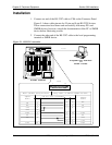
Installation
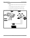
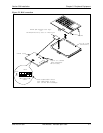
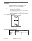
1. Connect one end of the RS-232C cable to CN6 on the Connector Panel.
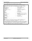
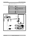
Figure 5-1 shows cable pinouts for 25-pin and 9-pin RS-232C devices.
These connections have been used successfully with many PCs and
SMDR devices; however, consult the documentation of the PC or SMDR
device before fabricating a cable.
2. Connect the other end of the RS-232C cable to the local programming
terminal or SMDR device.
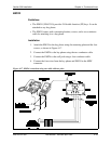
Figure 5-1. RS-232C connection
CN11
CN12
CN13
CN14
CN15
CN6
SW1
CN3
TRK1 TRK2 TRK3 EC1 EC2 EC3 EC4 EC5 EC6 EC7 EC8 EC/TRK SCC CPC AUX1 AUX2
CN5 CN4
CN2
CN1
CN1
RS-232C
M aster Cabinet
Programming Term inal
or
SM D R D evice
1
13
14
25
Main C abinet (C N 6) RS-232C
Prog.Term.orSMDR Printer RS-232C
Signal
Name
Pin N o. and C onnection
Signal
Name
DB-25
DB-25
DB-9
TD
RD
CTS
RTS
DSR
SG
CD
DTR
2
3
4
5
6
7
8
20
2
3
1
4
5
7
8
6
3
2
8
20
7
4
5
6
RD
TD
CD
DTR
SG
RTS
CTS
DSR
CN6