


Section 300-Installation Chapter 4. Trunks and Lines
DBS-2.3/9.2-300 DBS Manual - Revised April 2000 4-29
Installing T1 in a Double Cabinet with T1s in the Master and Slave
1. Install the Sync Unit in the master cabinet as described in Steps 1 and 2
under “Installation for a Single T1.”
2. Install a T1 MDF card in each cabinet. (See Step 3 on page 4-23.)
3. Set Switch 1 on the T1 cards. (See Step 4 on page 4-24.)
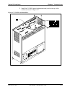
4. Install a T1 card in each “EC/TRK” slot.
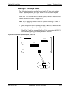
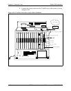
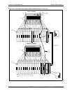
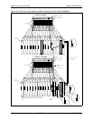
5. Connect the Clock Sync Cable from CN4 on the master-cabinet T1 to
CN5 on the slave-cabinet T1, as shown in Figure 4-12.
Note:
Part Number VB-43564 is used for the Clock Sync Cable when
T1s are installed in the master and slave cabinets.
6. At the master cabinet, connect the Sync Cable from CN1 on the Sync
Unit to CN5 on the T1 card (Figure 4-12).
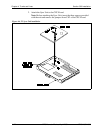
7. At each cabinet, connect the cable attached to CN3 on the T1 MDF card
to CN3 on the T1 card (Figure 4-10).
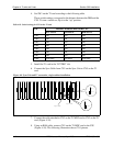
8. Using an RJ48 cable, connect CN1 of each T1 MDF card to a CSU. (See
Figure 4-9 on page 4-25 for RJ48 pinouts.)
9. For both cabinets, connect the ground cable from the T1 MDF card as
shown in Figure 4-10 on page 4-26.