


Section 300-Installation Chapter 5. Peripheral Equipment
DBS-2.3/9.2-300 DBS Manual - Revised April 2000 5-35
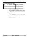
Table 5-11. Maximum distances for SLTA installation
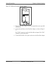
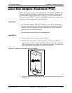
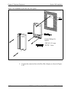
4. If the DBS is powered up, turn off the power.
5. Connect the GND and +24V leads on the SLTA to the DBS connector
panel.
Be sure the wires do not touch each other or touch the metal
frame housing
.
6. Turn on the DBS power.
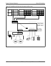
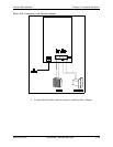
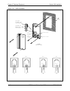
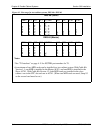
7. Connect the “T” and “R” leads to the digital extension ports on the DBS
as per Figure 5-21. One digital extension port is required for each SLT.
8. Connect the SLT “T” and “R” leads to the SLTs.
9. Install the cover on the SLTA.
Wiring
gauge
Max. distance (in feet) between
the DBS and SLTA
Max. distance (in feet) between
the SLTA and the SLT
AWG 22 300’ or 10 W 3000’ or 100 W
AWG 24 190’ or 10 W 1900’ or 100 W
AWG 26 120’ or 10 W 1200’ or 100 W