


Chapter 3. Cabinet Installation
Section 300-Installation
3-8 DBS Manual - Revised April 2000 DBS-2.3/9.2-300
Installation
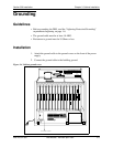
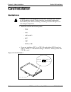
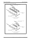
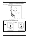
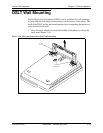
1. With the lettering on the card pointed up, position the card within the slot
guides. (See Figure 3-7.)
2. Hold the card on the top and bottom edges with both hands and carefully
push the card into the slot.
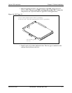
3. When the connector at the far end of the card touches the corresponding
connector on the backplane, press the card in until it is firmly seated.
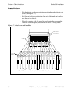
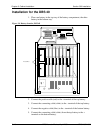
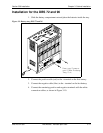
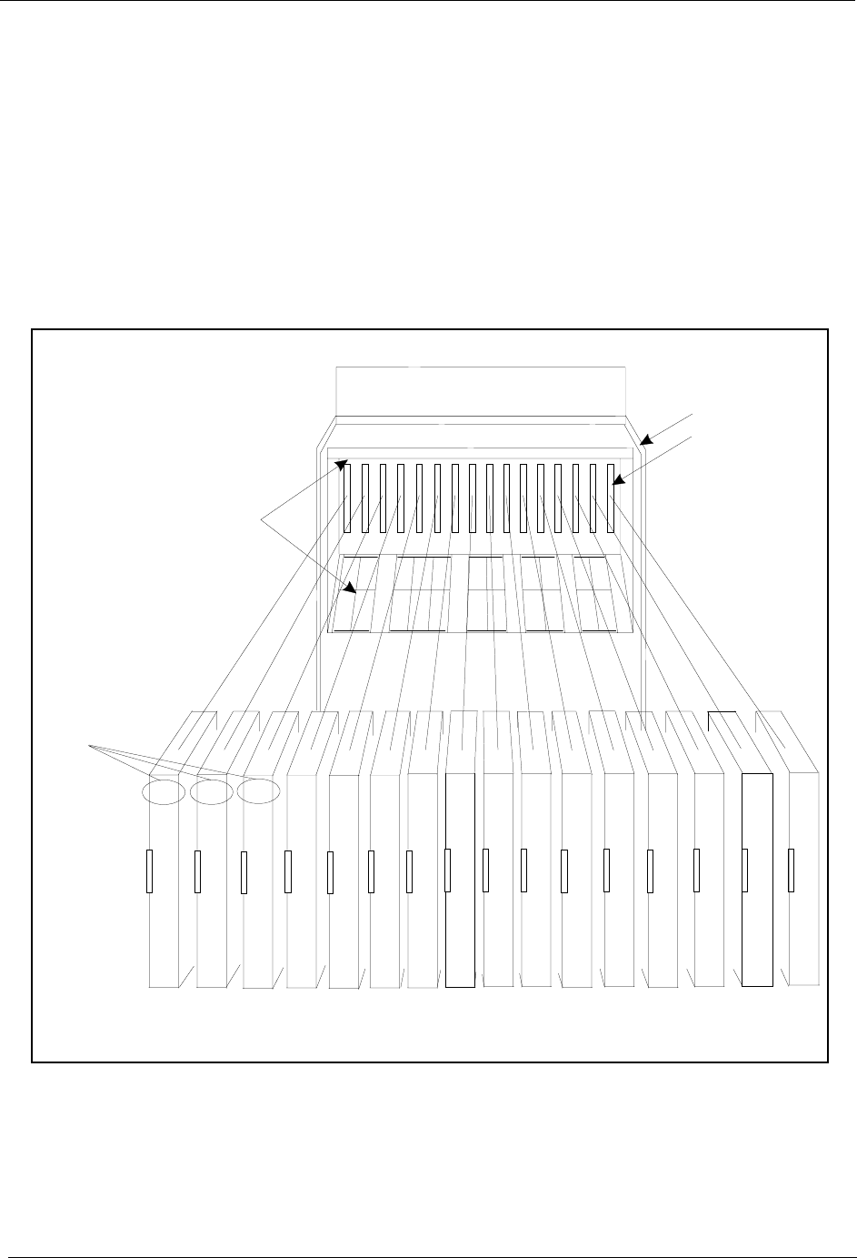
Figure 3-7. Printed circuit card installation
TRK1 TRK2 TRK3 EC1 EC2 EC3 EC4 EC5 EC6 EC7 EC8 EC/TRK SCC CPC AUX1 AUX2
TRK TRK
TRK
EC
*
EC EC EC EC EC EC EC
TRK
or
T1
or
EC
SCC
CPC
or
MFR#
MFR
or
API
API
or
CBL
or
MFR
Guide
Slot Label
C onnector
Card
Label
The M FR cardcanbeinstalled inthe C PC slotofslave cabinets.
*