


Section 300-Installation Appendix A. EX 1.0 Feature Update
DBS-2.3/9.2-300 DBS Manual - Revised April 2000 Page A-19
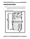
Additional Serial Port on CPC Card
Description
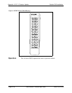
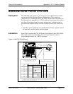
The CPC-EX card contains an on-board serial port (Serial Port 2) which
can be used for Bus Monitor/ Remote Maintenance. This serial port
(labeled CN5) is located just above the LEDs on the front of the card (see
the illustration on Appendix A:-4). This additional serial port allows you to
dial directly into the system for remote maintenance, without having to
disconnect the SMDR cabling from the backplane serial port (Serial Port
1).
• Serial Port 1 (the backplane port) and Serial Port 2 have separate controls
for baud rate, stop bit, parity, and data length
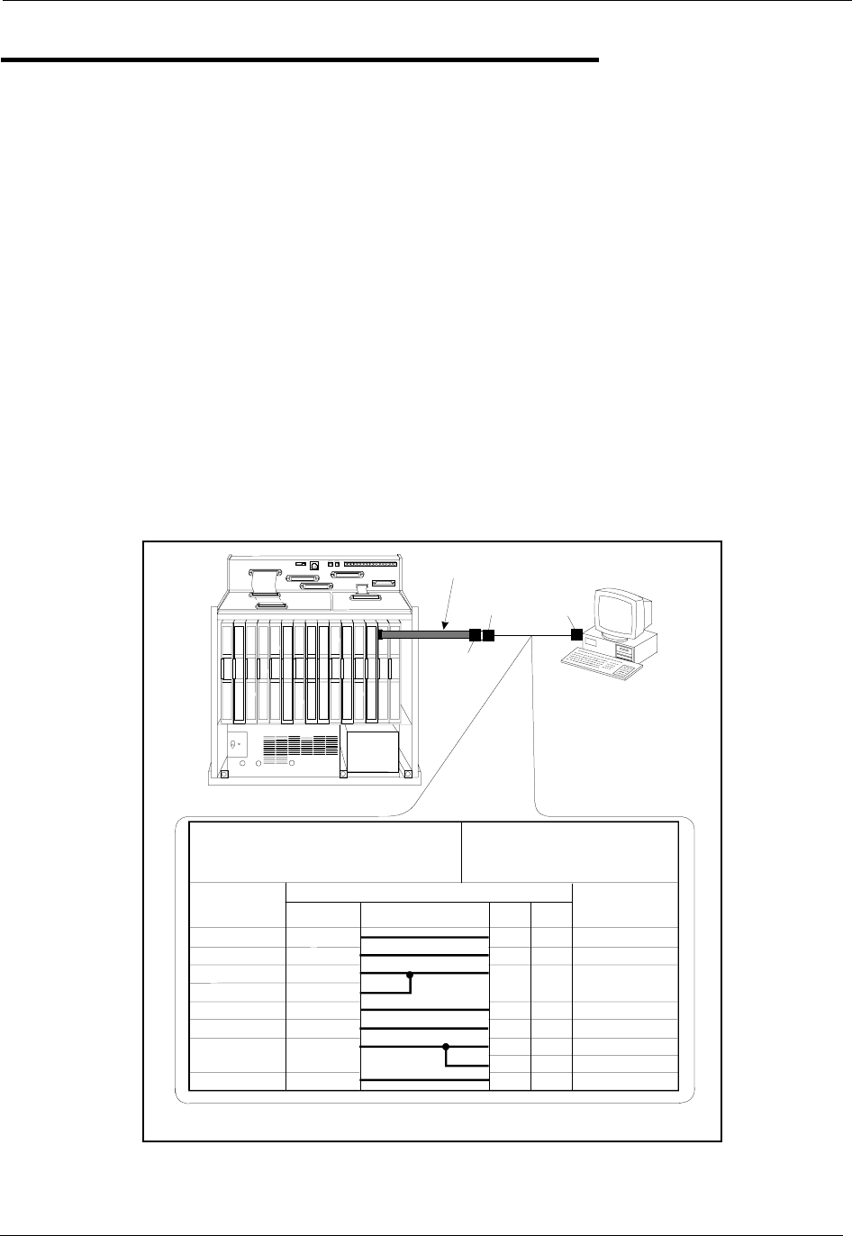
Installation
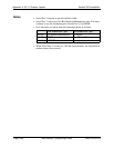
Serial Port 2 requires the CPC-EX Serial Port Adapter Cable (VB-43890).
This cable connects to Serial Port 2 via a 10-pin connector, and to a
programming terminal via a DB25 connector.
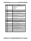
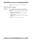
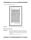
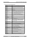
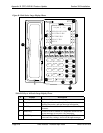
Figure A-10.CPC-EX Serial Port 2
CN11
CN12
CN13
CN14
CN15
CN6
SW1
CN3
TRK1 TRK2 TRK3 EC1 EC2 EC3 EC4 EC5 EC6 EC7 EC8 EC/TRK SCC CPC AUX1 AUX2
CN5 CN4 CN2
CN1
CN1
RS-232C
Master Cabinet
Programming Term inal
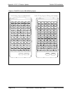
Serial Port Adapter CableEnd
(Requires DB-25 M ale)
Program m ing Term inal End
(Requires D B-9 or D B-25 M ale)
Signal
Name
Pin No. and C onnection
Signal
Name
DB-25
W/DB-25
Adapter
DB-9
TD
RD
N/C
CTS
DSR
SG
N/C
DTR
2
3
4
5
6
7
8
20
2
3
1
4
5
7
8
6
3
2
8
20
7
4
5
6
RD
TD
CD
DTR
SG
RTS
CTS
DSR
VB-43890
Adapter C able
DB-25
Male
DB-25
Fem ale*
DB-9or
DB-25 M ale
*The standardDBS SMDR/Maintenance cable(normally connected toCN6)maybe
connected tothe program m ing terminal.