


Section 300-Installation Chapter 4. Trunks and Lines
DBS-2.3/9.2-300 DBS Manual - Revised April 2000 4-7
Loop-Start Trunks
Guidelines
• Two versions of the loop-start trunk are available: the four-port version
(VB-43510) and the eight-port version (VB-43511).
• The following procedure covers loop-start trunk installation using the main
trunk connector. For instructions on using the expansion trunk connector,
see “Trunk and Line Expansion” on page 4-44
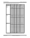
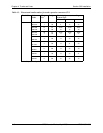
• For pinouts and color codes for the main trunk connector, see Table 4-2 on
page 4-5.
Installation
Installation without Caller ID
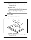
1. If installing VB-43511A Loop Start Card:
a. Remove the cover from the L-TRK card (VB-43511A).
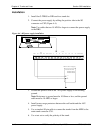
b. Set the all option switches to ON as shown in Figure 4-2.
c. Replace the cover on the L-TRK card (VB-43511A).
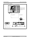
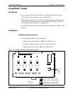
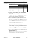
Figure 4-2. L-TRK Card Strap J1 and Switch Locations
ON ON ON ON
ON
ON
ON ON ON ON
L-TRK Card
(VB-43511A)
SW1 SW3
SW5
SW2
SW4 SW6 SW8
SW7
TK1
TK2 TK3 TK4 TK5 TK6 TK7 TK8
When a Caller ID Card Is Installed,
Set All Switches to the
OFF
Position
When No Caller ID Card Is Installed,
Set All Switches to the
ON
Position
J1
Strap J1
must be
cut to
receive
Caller ID