


Chapter 4. Trunks and Lines
Section 300-Installation
4-24 DBS Manual - Revised April 2000 DBS-2.3/9.2-300
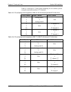
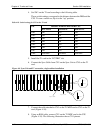
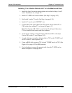
4. Set SW1 on the T1 card according to the following table.
These switch settings correspond to the distance between the DBS and the
CSU. To turn a switch on, flip it to the “up” position.
Table 4-18. Switch settings for SW1 on the T1 card
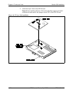
5. Install the T1 card in the “EC/TRK” slot
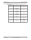
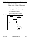
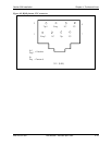
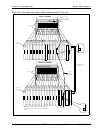
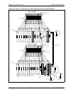
6. Connect the Sync Cable from CN1 on the Sync Unit to CN5 on the T1
card.
Figure 4-8. Sync Unit and T1 connection, single-cabinet installation
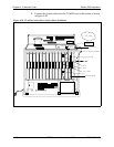
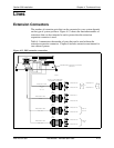
7. Connect the cable attached to CN3 on the T1 MDF card to CN3 on the T1
card (Figure 4-10).
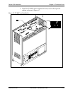
8. Using an RJ48 cable, connect CN1 on the T1 MDF card to the CSU
(Figure 4-10). The following illustration shows CN1 pinouts.
SW Distance from the DBS to the CSU
0 to 150 ft. 150-450 ft. 450-655 ft.
SW1 On Off Off
SW2 Off On Off
SW3 Off Off On
SW4 Off On Off
SW5 Off Off On
SW6 Off On Off
SW7 Off Off On
SW8 Not used Not used Not used
TRK
DEC DEC
DEC DEC
DEC
DEC DEC
DEC T1
TRK
SCC
CPC
MFR
N
O
T
U
S
E
D
Sync.Unit
CN5
CN1
S.U.
SyncCable