


Chapter 5. Peripheral Equipment
Section 300-Installation
5-20 DBS Manual - Revised April 2000 DBS-2.3/9.2-300
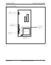
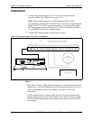
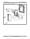
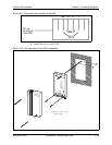
Figure 5-10. Cable punch-out plate, Power Failure Unit
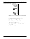
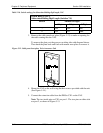
3. Mount the PFU on the wall using the three screws provided with the unit.
(See Figure 5-11.)
4. Connect the trunks from the central office to the PFU.
5. Connect the SLTs to the AEC extension ports on the PFU.
6. Connect the trunks from the DBS to the PFU.
7. Connect the AEC ports from the DBS to the PFU.
When a power failure occurs, AEC “A” is switched to Trunk “A,” AEC
“B” is switched to Trunk “B,” and so on.
8. Connect the +24V and GND terminals from CN2 on the DBS Connector
Panel to the PFU.
9. Install the cover on the PFU.