


Section 300-Installation Chapter 4. Trunks and Lines
DBS-2.3/9.2-300 DBS Manual - Revised April 2000 4-27
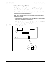
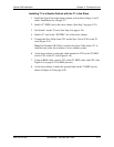
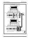
Installing T1 in a Double Cabinet with the T1 in the Slave
1. Install the Sync Unit in the master cabinet as described in Steps 1 and 2
under “Installation for a Single T1.”
2. Install a T1 MDF card in the slave cabinet. (See Step 3 on page 4-23.)
3. Set Switch 1 on the T1 card. (See Step 4 on page 4-24.)
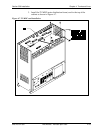
4. Install a T1 card in the “EC/TRK” slot of the slave cabinet.
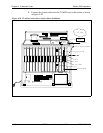
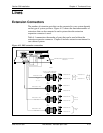
5. Connect the Sync Cable from CN1 on the Sync Unit to CN5 on the T1
card (Figure 4-11).
Note:
Part Number VB-43564 is used for the Sync Cable when a T1 is
installed only in the slave cabinet of a two-cabinet system.
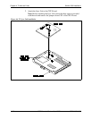
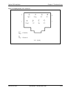
6. At the slave cabinet, connect the cable attached to CN3 on the T1 MDF
card to CN3 on the T1 card (Figure 4-10).
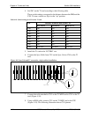
7. Using an RJ48 cable, connect CN1 of the T1 MDF card to the CSU. (See
Figure 4-9 on page 4-25 for RJ48 pinouts.)
8. At the slave cabinet, connect the ground cable on the T1 MDF card as
shown in Figure 4-10 on page 4-26.