


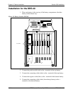
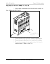


Chapter 3. Cabinet Installation
Section 300-Installation
3-18 DBS Manual - Revised April 2000 DBS-2.3/9.2-300
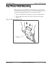
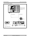
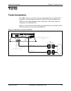
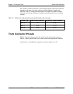
Test Phone
Guidelines
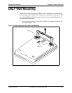
• The test terminal (CN3) on the DBS Connector Panel can be used to
connect a display phone for programming.
The test terminal can be used for initial programming before extension
cabling is completed.
• The test terminal is turned on by flipping SW1 on the Connector Panel to
the “Test” position. When SW1 is in the test position, extension ports 7
and 8 are connected through the test terminal. When SW1 is not in the test
position, extension ports 7 and 8 are connected through the MDF.
Note:
Before using the test terminal on a DBS that is operational, be sure
the phones connected to ports 7 and 8 can be taken out of service.
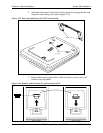
• A DSS/72 can be connected to the display phone for text entry. Port 7 must
be assigned as extension 101 and the DSS/72 must be assigned as
telephone type 13 for the DSS/72 to operate.
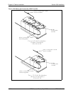
Installation
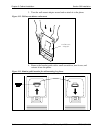
1. Connect the telephone and DSS (optional) to CN3 on the Connector
Panel. (See Figure 3-18 on page 3-19.)
2. Set SW1 to “Test.”
3. When programming is completed, set SW1 back to “ST.”