


Chapter 4. Trunks and Lines
Section 300-Installation
4-8 DBS Manual - Revised April 2000 DBS-2.3/9.2-300
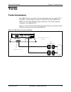
2. Install the loop-start trunk in a trunk slot.
3. Use a standard 50-pin cable to connect the trunks from the MDF to the
main trunk connector CN1.
Installation with Caller ID
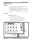
1. Remove the cover from the L-TRK card (VB-43511A). This cover should
be set aside since it cannot be reinstalled with a Caller ID Board installed.
2. Cut strap J1 on the L-TRK card as shown in Figure 4-2.
3. Set switches SW1 through SW8 on the L-TRK card (VB-43511A) to
OFF.
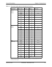
4. Attach the Caller ID card to the L-TRK card.
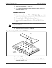
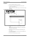
Figure 4-3. Attaching Caller ID Card to the L-TRK Card
5. Install the L-TRK card in a trunk slot.
6. Use a standard 50-pin cable to connect the trunks from the MDF to the
main trunk connector CN1.
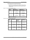
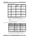
IMPORTANT: When caller ID is used, you must correctly set the switches to prevent possible
damage to the L-TRK card.
Caller
ID Board
(VB-43551)
L-TRK Card
(VB-43511A)