


Chapter 6. Double-Cabinet Systems
Section 300-Installation
6-4 DBS Manual - Revised April 2000 DBS-2.3/9.2-300
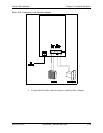
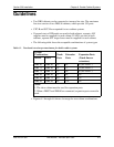
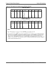
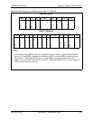
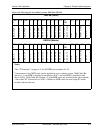
Figure 6-1. Slot usage for two-cabinet systems, DBS 40 + DBS 40
DBS 40 (Slave
)
DBS 40 (Master)
Notes:
*See “T1 Interface” on page 4-11 for EC/TRK port numbers for T1.
#
A maximum of two MFR cards can be installed in a two-cabinet system. With Cable Kit
Version 1.1, one MFR is installed in the Master AUX1, and one MFR is installed in the
Slave AUX1. With Cable Kit Version 1.2, both MFR cards are installed in the slave
cabinet--one in the CPC slot and one in AUX1. (When two MFR cards are used, Strap S3
on the second card must be cut.)
TRK1 EC1 EC2 EC3 EC/TRK SCC CPC AUX1 AUX2
TRK 9-16
EXT 25-32
EXT 33-40
EXT 41-48
TRK 17-24* or
EXT 49-56
N/A
MFR
#
MFR
#
CBL-S
TRK1 EC1 EC2 EC3 EC/TRK SCC CPC AUX1 AUX2
TRK 1-8
EXT 1-8
EXT 9-16
EXT 17-24
N/A
SCC-B
CPC-B
MFR
#
or API
CBL-M