XTP SR HDMI Scaling Receiver • Operation 12
Operation
This section contains information for front panel operation and configuration of the
XTP SR HDMI and configuration through the On-Screen Display (OSD) menu. Topics in this
section include:
• Front Panel Features and Indicators
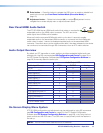
• Rear Panel HDMI Audio Switch
• Audio Output Overview
• On-Screen Display Menu System
• Front Panel Lockout Mode (Executive Mode)
Front Panel Features and Indicators
XTP
HDCP
SIGNAL
AUDIO
HDMI
HBR
S/PDIF
BITSTREAM
ANALOG
LPCM
XTP SR HDMI
MENU ENTER
ADJUST
CONFIG
ADJ
X
X
X
XTP
U
ST
Front Panel
CD EF GA B
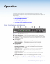
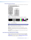
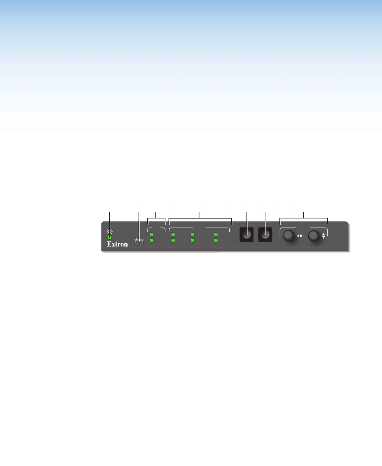
Figure 9. XTP SR HDMI Front Panel
A
Power LED indicators — Lights when power is applied to the unit. There are two
Power LED indicators, one on the front panel and one on the left side of the rear panel.
B
Config port — If desired, connect a host device to the front panel USB mini-B port for
configuring the switcher.
C
XTP indicators:
Signal LED indicator — Lights when an active XTP input signal is received.
HDCP LED indicator — Lights when the received input signal is encrypted.
D
Audio indicators:
HBR LED indicator — Lights when the audio input is high bit rate audio.
Bitstream LED indicator — Lights when the embedded audio signal format is a
Dolby
®
Digital, DTS, or 2-Ch Dolby.
LPCM LED indicator — Lights when the embedded audio signal is LPCM-2Ch.
HDMI LED indicator — Lights when the audio input signal is multi-channel,
LCPM-2Ch, or HiDef audio.
S/PDIF LED indicator — Lights when the input audio format is multi-channel or
LPCM.
Analog LED indicator — Lights when the received audio format is LPCM.
E
Menu button — Press this button to navigate the OSD menu or enable or disable front
panel lockout mode (see Front Panel Lockout Mode (Executive Mode) on
page 19).


