


XTP SR HDMI Scaling Receiver • Installation 4
Installation
This section contains installation procedures for the XTP SR HDMI and wiring details. Topics
in this section include:
• Rear Panel Connectors
• Making Connections
The XTP SR HDMI can be placed on a tabletop or mounted in a rack or under a desk (see
Mounting on page 43).
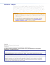
Rear Panel Connectors
LAN
SIG LINK
XTP IN
POWER
12V
HDMI
1.0 A MAX
Rx GTx
RS-232 IR
RxTx
−+−+
LR
1
2
OVER XTP
AUDIO
OFF
ON
S/PDIF
RESET
RS-232
Tx Rx G
REMOTERELAYS
OUTPUTS
AUDIO
IABC DEFG
H
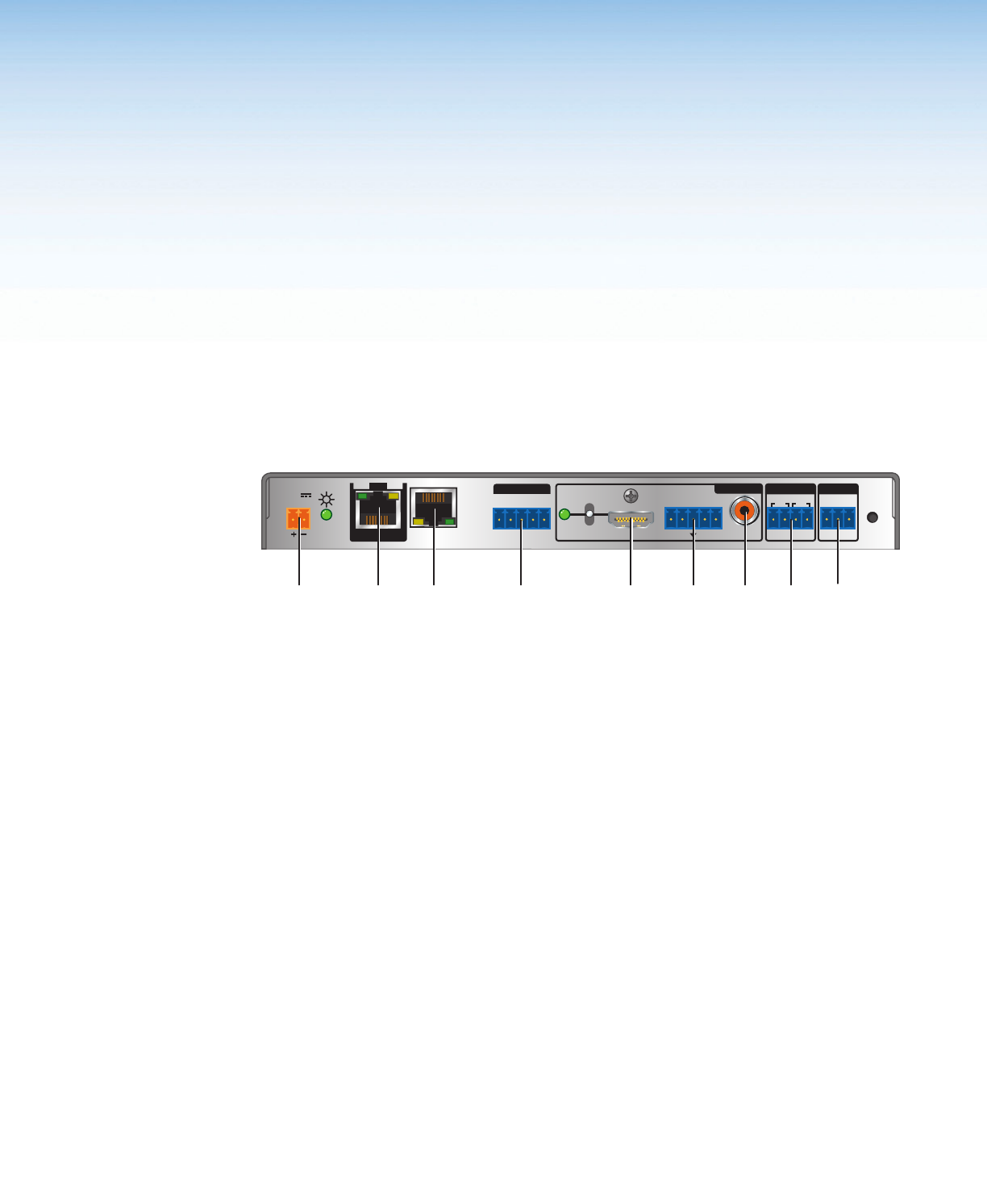
A
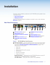
XTP input connector (page 4)
B
LAN connector (page 5)
C
RS-232 and IR Over XTP connector
(page 5)
D
HDMI output connector (page 5)
E
Analog audio output connector
(page 5)
F
S/PDIF audio output connector
(page 6)
G
Relay connectors (page 6)
H
Remote RS-232 connector (page 6)
I
DC power connector (page 6)
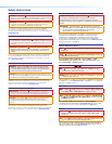
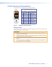
Figure 2. XTP SR HDMI Rear Panel Connectors
A
XTP input connector — Connect a twisted pair cable to the RJ-45 connector labeled
XTP IN on the XTP SR HDMI and the XTP output port on another XTP device to pass
all signals (see TP Cable Termination and Recommendations on page 7). This
cable carries the following signals:
• Digital video
• Digital audio
• Bidirectional RS-232 and IR commands
• Remote power
• Ethernet communication
• System communication
Signal LED indicator — Lights green when the XTP SR HDMI receives an active XTP
input signal from a compatible transmitter or matrix switcher.
Link LED indicator — Lights yellow when a valid XTP link is established.