


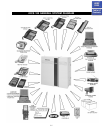

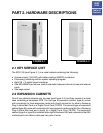

FIGURE 1–1
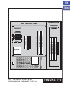
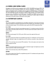
FIGURE 1–2
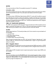
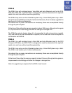
1.5
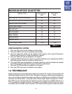
SEITITNAUQECIVEDMUMIXAM
EPYTECIVEDTUOHTIWUSP
MVS
HTIWUSP
MVS
)SECIVEDILD&S'TLS(SNOITATS6584
)SMIPD/SMOA/STESYEK(SECIVEDILD6584
SENOHPELE
TENILELGNIS2443
SENILTRATSPOOL6363
STIUCRICIRB4242
SLENNAHCIRB8484
SKNURTM&E2121
STROP8-iMVS08
STROP4-iMVS04
sknurTlatigiD
IRP/1T)42(1)42(1
TABLE 1–1
CONFIGURATION NOTES
1. Only one 2 SLI card can be installed in the system.
2. Only one SMISC card can be installed in the system.
3. Up to six expansion cards can be installed in the system with a type B Expansion
Cabinet and five slots for a type A Expansion Cabinet.
4. Only one SVM card can be installed in the system.
5. Installing SVMi-8 reduces the maximum number of stations by 8. Installing the SVMi-4
card reduces the maximum number of stations by 4.
6. Only eight KDbs can be installed in the system and they must be installed on keysets
connected to the (8) eight 2B+D ports on the KSU motherboard.
7. Only one TE/PRI card can be installed in the system.
8, Only one ITMC card can be installed in the system.
1.2 TECHNOLOGY
System switching is accomplished by means of a custom IC “engine” that provides 128
switchable digital channels. Each of the 128 digital channels is automatically assigned to
carry voice or data as required by system operation in a PCM format. In addition to the 128
channels mentioned above , the system also utilizes Digital Signal Processors or DSPs.
Each DSP may be configured by the switching control program as a DTMF receiver or a
C.O. tone detector on a per-call basis. The engine chip contains four DSPs and four more
are added when an SMISC card is installed. This means that the system contains a total of
HOME
PAGE
Table of
Contents