


Effective December, 1998
IL 33-K2C-1
Page 8
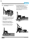
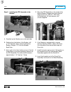
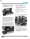
Step 6: Installing the DTA Assembly in the
Breaker
A. Carefully lay the Breaker over on its right side.
B. Working from the bottom of the Breaker, drill
a .312" diameter hole in each of the bottom
Breaker Flanges 1.75" from the Breaker
Back Plate.
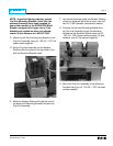
C. Cut a notch in the front, bottom corner of the left
Phase Barrier to provide operating clearance for
the DTA Assembly. The notch should measure
approximately 1 1/4" high by 1" deep.
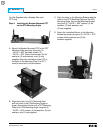
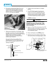
D. Mount the DTA Assembly on the inside of the
bottom Breaker Flanges using the holes just
drilled and the (2) .250-20 × .750" bolts,
(4) flat washers, (2) lock washers, and
(2) nuts supplied.
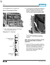
E. If the Breaker is equipped with a original
left hand Auxiliary Switch, observe the Drive
Link orientation then remove and scrap the
Drive Link.
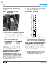
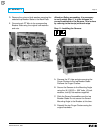
F. Install the tension spring and (1) flat washer on
the threaded end of the new Breaker Reset
Assembly supplied with the Retrofit Kit.
G. Insert the threaded end of the Reset Rod
Assembly into the slot in the Reset Assembly.