


Effective December, 1998
IL 33-K2C-1
Page 19
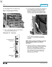
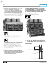
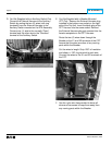
G. Route the DTA Harness down to the 2-Point
Terminal Block mounted to the DTA Assembly.
Connect the “+” wire to the same terminal as
the “+” wire from the DTA. Connect the
unmarked wire to the same terminal as the
unmarked wire from the DTA.
H. Use the nylon wire ties provided to dress all
wires and harnesses to keep them away from
any moving parts within the Breaker.
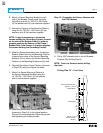
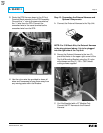
Step 13: Connecting the External Harness and
Optional Components
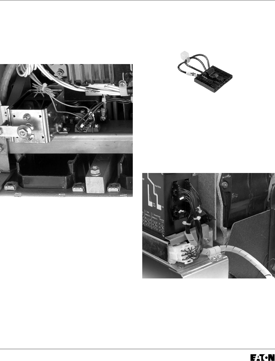
A. Connect the External Harness to the Trip Unit.
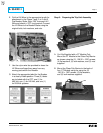
NOTE: For 510 Basic Kits, the External Harness
is the plug pictured above. It is to be plugged
into the right side of the Trip Unit.
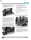
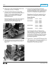
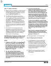
B. Secure the External Harness to the two (2)
pre-drilled holes in the upper right corner of the
Trip Unit Mounting Bracket using the (2) nylon
wire clamps and the (2) .138 × .380" thread
cutting screws supplied.
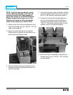
C.
For Kits Supplied with a PT Module Only.
Connect the PT Harness to the External
Harness.