


Effective December, 1998
IL 33-K2C-1
Page 4
Step 1: General Breaker Preparation
Before attempting to remove the Breaker from the
Cell or perform any Retrofit operation, be sure to
read and understand the Safety Precautions
section of this manual. In addition, be sure to read
and understand the Instructions for the Application
of Digitrip RMS Retrofit Kits on Power Circuit
Breakers (Retrofit Application Data - Publication
AD 33-855-1), supplied with the Digitrip Retrofit Kit.
!
WARNING
DO NOT ATTEMPT TO INSTALL OR PERFORM
MAINTENANCE ON EQUIPMENT WHILE IT IS
ENERGIZED. SEVERE PERSONAL INJURY OR
DEATH CAN RESULT FROM CONTACT WITH
ENERGIZED EQUIPMENT. VERIFY THAT NO
VOLTAGE IS PRESENT BEFORE PROCEEDING.
A. Trip the Breaker and remove it from the Cell.
Move the Breaker to a clean, well-lit work
bench.
NOTE: It is the responsibility of the Retrofitter
to insure that the Breaker and all original
components are in good condition. Visually in-
spect all Breaker components for signs of dam-
age or wear. If any signs of damage or wear are
detected for components not included in the
Retrofit Kit, secure the necessary replacement
parts before beginning the Retrofit Process.
The force necessary to trip the Breaker should
not exceed three (3) lbs.
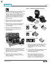
To begin the Retrofit Process, refer to the compo-
nents list at the end of this manual. Lay out the
components and hardware according to the steps
outlined. The components and hardware will be
used to complete each step in the Retrofit Process.
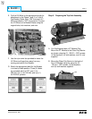
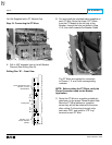
Step 2: Removing the Original
Electromechanical Trip Units
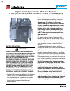
NOTE: For all photographs contained within
this manual, an ITE K-1600 Black Breaker
(without trigger fuses) was used as the
subject. Depending on the version and age
of the Breaker being Retrofitted, some
components / views may differ from those
depicted in the manual.
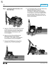
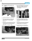
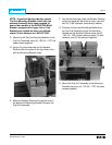
A. For Breakers equipped with a Secondary
Contact Bracket, move the back of the Breaker
near the edge of the work bench. Remove the
two (2) screws securing the top of the
Secondary Contact Bracket. Loosen the two
(2) bottom screws then rotate the bracket
down over edge of work bench.
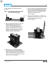
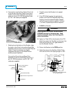
B.
Remove the “E” clips then the pins securing
the Finger Clusters to the Bottom Breaker
Stabs. Remove the Finger Clusters. Set all
parts aside for reinstallation later in the
Retrofit Process.