


Effective December, 1998
IL 33-K2C-1
Page 9
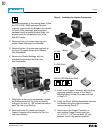
Drive Link to Optional
Auxiliary Switch
Cotter Pin
Pin
Washer
Cotter Pin
Washer
Pull Shaft Stop
Reset Rod Assembly
Adjust Nuts for Proper Reset
DTA Reset
0.06"
0.500"
Notch
Phase
Barriers
Breaker Trip Bar
Trip Plate
DTA
Assembly
Closed
Open
Must have a Gap when Breaker
is in the Open Position
Square
Spacers
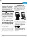
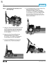
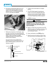
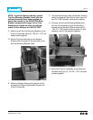
H. Connect the new Auxiliary Switch Drive Link
to the left hand Auxiliary Switch (be sure to
install it in the same orientation as original)
using the (1) pin, (2) .250 flat washers, and
(2) .06 × .88" cotter pins supplied.
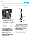
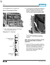
I. Working from the bottom of the Breaker, align
the holes in the Drive Link and the Reset Rod
Assembly with the hole in the Pull Shaft Stop as
shown. It may be necessary to slightly
compress the spring on the Reset Rod to
achieve proper alignment.
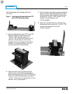
Connect the Drive Link and Reset Rod
Assembly to the Pull Shaft Stop using the (1)
pin, (2) .250 flat washers, and (2) .06 × .88"
cotter pins supplied.
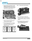
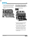
J. Carefully return the Breaker to its upright
position.
K. If the DTA Shaft touches the work bench
surface, shim the DTA Assembly Mounting
Angle up from the bottom Breaker Flanges
using the square spacers supplied. Use one
(1) or two (2) spacers per side as required.
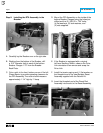
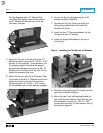
L. CLOSE the Breaker.
Guard against the Breaker unintentionally
OPENING during the following step. Keep
hands and fingers away from moving parts
within the Breaker.
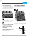
M. Apply Loc-Tite
®
242 to the threads of the DTA
Shaft then adjust the Trip Plate on the top of the
Shaft so that there is a .06" gap between it
and the Breaker Trip Bar.
N. Return the Breaker to the OPEN position.
O. Adjust the nuts on the Auxiliary Switch Drive
Link until the Drive Link Spring length is .500".
!
WARNING