


Effective August, 1998
IL 33-K2C-1
Page 29
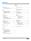
INDEX
A
Auxiliary Switch -
Aux. Switch Arm, photo........................................6
Installing on DTA Mounting Angle.........................6
B
Breaker -
and Choosing a Retrofit Kit...................................3
General Breaker Preparation................................4
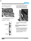
Installing Retrofitted Breaker
in the Cell............................................................22
photo.....................................................................1
C
Copper Connectors -
Installing of...........................................................5
photos...................................................................5
CPT, Breaker Mounted -
Connecting to Breaker Stabs................................9
Installing on DTA Mounting Angle.........................7
D
Drive Link Connection.................................................9
Drive Link Spring Length.............................................9
DTA Assembly -
Installing in the Breaker........................................8
Installing on Mounting Angle................................6
E
External Harness, photo...........................................19
F
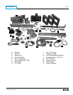
Family Photo.............................................................27
H
Harnesss -
Cell Harness Mounting.......................................21
Connecting External Harness
and Optional Components..................................19
Connecting Sensor Harness
& DTA Harness...................................................17
HV Wires -
Connection to Top Breaker Stabs.......................11
I
ICON Identification Table.............................................3
K
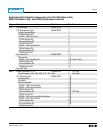
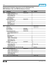
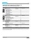
Kit Components Table.................................................2
Kit Components Parts List.........................................22
P
Power Convention.......................................................9
PT Module Attachment..............................................12
PT Wires Attachment................................................14
S
Safety Precautions......................................................1
Sensors -
Installing on Breaker Stabs
Top Mounted................................................15
Bottom Mounted 16
Style Numbers....................................................18
T
Tension Spring............................................................8
Testing the Breaker...................................................21
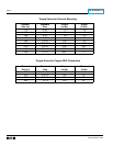
Torque Tables............................................................26
Trip Units -
Installing on the Breaker.....................................12
and Mounting Brackets.......................................13
Trip Unit Assembly..............................................11
Removing Original Trip Units................................4
V
Voltage Warning Labels............................................11