


Effective December, 1998
IL 33-K2C-1
Page 22
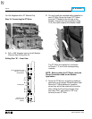
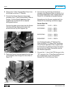
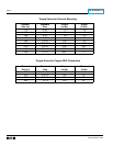
Digitrip Retrofit Kit Installation Components for the ITE K-1600 (Black or Red),
KDON-1600 (Black or Red), and K-2000 (Red) Breakers
Step Description Style No. Qty. Comment
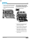
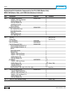
Step 3 Copper Connector K-1600 Black 8259A13G03 3 K-1600 Black Kits
Copper Connector K-1600 Red 8259A13G04 3 K-1600 Red Kits
Copper Connector K-2000 Red 8259A13G05 3 K-2000 Red Kits
Copper Connector KDON-1600 Red 8259A13G06 3 KDON-1600 Red Kits
.312-18 × 1.12 Hex Cap Screw 12 K-1600 Black & Red Kits
.312-18 × 1.75 Hex Cap Screw 12
K-2000 Red & KDON-1600 Red Kits
.312 Flat Washer Stl. 12
.312 Lock Washer Stl. 12
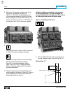
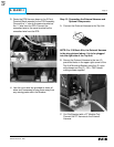
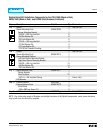
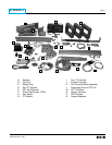
Step 16: Installing the Retrofitted Breaker
in the Cell
!
WARNING
Do not leave the Breaker in an intermediate
position in the switchgear cell. Always leave it
in the CONNECTED, DISCONNECTED, or
(Optional) TEST position. Failure to do so could
lead to improper positioning of the Breaker
and flashover, causing death, serious personal
injury, and / or property damage.
NOTE: It is the responsibility of the Retrofitter
to insure proper Breaker / Cell fit. When
racking the Breaker into the Connected
position, the Retrofitter MUST FOLLOW BOTH
the manufacturer’s instructions and the
customer’s safety standards and procedures for
racking a Breaker into the Connected
position.
A. With the Breaker in the Open position and the
springs discharged, slowly rack the Breaker into
the Connected position, making sure there is no
interference or binding. The Breaker should rack
smoothly and without mechanical interference
between any Breaker and Cell parts. The
Retrofitter will feel some resistance when the
primary fingers connect onto the stabs of the
Cell. This is normal.
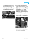
However, if any unusual resistance is detected
that could be abnormal interference between
the Breaker and Cell parts, stop immediately
and move the Breaker out of the Connected
position. Examine what is causing the
interference and correct the situation.