


Effective December, 1998
IL 33-K2C-1
Page 11
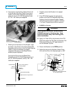
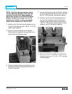
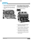
E. Cut the HV Wires to the appropriate length for
attachment to the Phase 1 and 2, or 2 and 3
Top Breaker Stabs. Strip .250" from each HV
Wire and attach a .375" ring terminal. Connect
the HV Wires to the Breaker Stabs using the
original bolts, lock washers, and nuts.
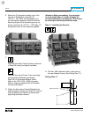
F. Use the nylon wire ties provided to dress the
HV Wires and keep them away from any
moving parts within the Breaker.
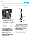
G. Attach the appropriate label for the Breaker
in a clearly visible position. Three (3) labels
are included with the CPT, one (1) for
480 Volt, one (1) for 240 Volt, and one (1)
for 208 Volt systems.
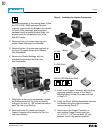
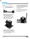
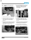
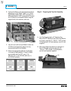
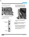
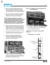
Step 8: Preparing the Trip Unit Assembly
A.
For Kits Supplied with a PT Module Only.
Mount the PT Module to the Glass Poly Barrier
as shown using the (2) .138-32 × .500" screws,
(4) flat washers, (2) lock washers, and (2) nuts
supplied.
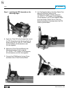
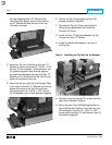
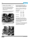
B. Mount the Glass Poly Barrier to the back of
Aux. CT Module using the using the (2)
.190-32 × .380" screws, (2) flat washers,
and (2) lock washers supplied.