


Effective December, 1998
IL 33-K2C-1
Page 10
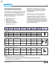
.50
.438 dia. (1) for
HV Wires
Existing Slot
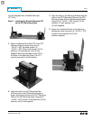
For Kits Supplied with a Breaker Mounted
CPT Only.
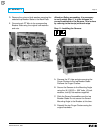
Step 7: Connecting the CPT to the
Breaker Stabs
A. Position the fuses in an accessible location then
mark and cut the Load Side of each High
Voltage Fused Wire (HV Wire). Strip .250" from
each Load Side HV Wire and attach a .138" ring
terminal to each. Attach the HV Wires to the
CPT terminals to achieve the required
voltage. (See the following Table.)
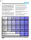
Voltage Required CPT Terminals Used
480 Volt Circuit H1 & H4
240 Volt Circuit H1 & H3
208 Volt Circuit H1 & H2
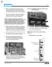
NOTE: The power convention of the ITE
K-1600 / 2000 is normally Top to Bottom,
meaning the Top Breaker Stabs are on the
Line Side of the Breaker and the Bottom
Breaker Stabs are on the Load Side.
The HV Wires from the CPT MUST BE
ATTACHED to the Line Side of the Breaker. If
it is determined that the power flow for the
Breaker application is opposite the normal
convention, the HV Wires must be attached
to the Bottom Breaker Stabs.
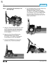
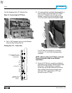
B. Drill a .438" diameter hole in the right Breaker
Channel (See Drilling Plan A).
Drilling Plan “A” – Front View
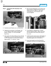
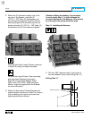
C. Route the HV Wires up through the Breaker,
then through the hole just drilled towards the
Phase 1 and 2, or 2 and 3 Top Breaker Stabs.
NOTE: The Line Side HV Wires are longer than
necessary and are cut during the following
steps. Before cutting the wires, be sure that
sufficient length is left so that the HV Wire
Fuses are accessible from the front of the
Breaker and that the connections can be made
to the correct Breaker Stabs.
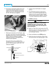
D. Remove the nuts and lock washers from the
bolts securing the Phase 1 and 2, or 2 and 3
Top Breaker Stabs to the Back Plate.