


Effective December, 1998
IL 33-K2C-1
Page 14
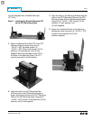
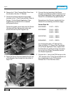
For PT Module Kits Only
.438 dia. (1) for PT
Module Wires
1.12
.50
.438 dia. (1) for
Sensor Harness
(All Kits)
Existing Slot
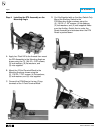
For Kits Supplied with a PT Module Only.
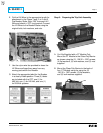
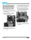
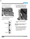
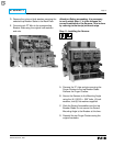
Step 10: Connecting the PT Wires
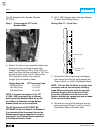
A. Drill a .438" diameter hole in the left Breaker
Channel (See Drilling Plan B).
Drilling Plan “B” – Front View
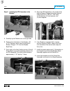
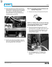
B. Cut and install the insulated tubing supplied on
each PT Wire. Route the three (3) PT wires
from the PT Module to the left rear of the
Breaker, through the hole just drilled in Step
10-A, then down towards the Breaker Stabs.
The PT Wires are marked for connection
to Phases 1, 2, and 3 with corresponding
numbers.
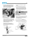
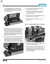
NOTE: Before cutting the PT Wires, verify the
Phase Convention used on the Breaker
Application.
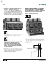
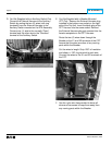
C. Route the PT Wires to a position suitable for
attachment to the proper Phase Breaker Stab.
Move the PT Wire markers to a position
where they will still be attached to the wires
after cutting. Cut the wires to length, strip
each wire .250", and install a .375" ring
terminal to each PT Wire.