


Effective December, 1998
IL 33-K2C-1
Page 20
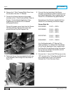
D.
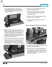
For Kits Supplied with an Auxiliary Switch Only.
Connect the External Harness to the Auxiliary
Switch by routing the two (2) wires (with ring
terminals) from the External Harness to the
Auxiliary Switch mounted on the DTA Assembly.
Connect one (1) wire to the normally “Open”
terminal and the other wire to the “Common”
terminal of the Auxiliary Switch.
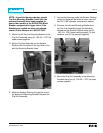
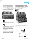
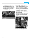
E.
For Kits Supplied with a Breaker Mounted
CPT Only.
Remove the External Harness plug
installed in the bottom rear socket on the right
side of the Trip Unit. Insert the black plug of the
CPT Harness into the same socket. Reinsert
the External Harness plug just removed into the
female receptacle on the CPT Harness.
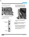
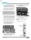
Route the two (2) wires down through the
Breaker to the X1 and X2 terminals of the CPT.
Assure that the wires are clear of any moving
parts within the Breaker.
Cut the wires to length. Strip .250" of insulation
and attach a .138" ring terminal to each wire.
Connect the wires to the X1 and X2 terminals of
the CPT.
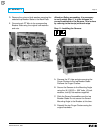
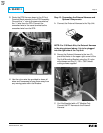
F. Use the nylon wire ties provided to dress all
wires and harnesses to keep them away from
any moving parts within the Breaker.