


Effective December, 1998
IL 33-K2C-1
Page 17
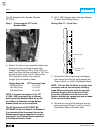
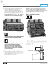
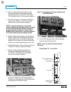
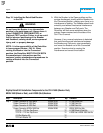
For PT Module Kits Only
.438 dia. (1) for PT
Module Wires
1.12
.50
.438 dia. (1) for
Sensor Harness
(All Kits)
Existing Slot
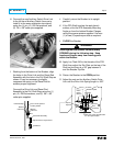
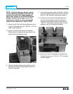
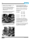
B. Mount a Sensor Mounting Bracket to each
side of the Breaker Frame using the holes
just drilled and the (4) .250-20 × .500" bolts,
(4) flat washers and (4) lock washers supplied.
C. Secure the Sensors to the Mounting Platform
using the (6) .250-20 × .500" bolts, (6) lock
washers, and (6) flat washers supplied.
NOTE: It may be necessary to loosen the
screws holding the Grounding Contact (located
on the side of the Breaker Frame) in order to
properly position the Sensor on the Phase 1
Breaker Stab. After Sensor is in place retighten
the screws holding the Grounding Contact.
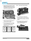
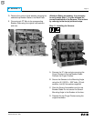
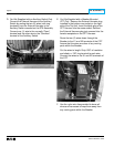
D. Slide the Sensor Assemblies over the bottom
Breaker Stabs. Be sure the Mounting Platform
is above the surface of the Sensor Mounting
Brackets. Do not secure the Sensor Mounting
Platform to the Mounting Brackets at this time.
E. Reinstall the bottom Finger Clusters (removed
in Step 2-B) using the original hardware.
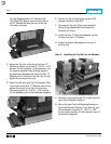
F. Mount the Sensor Mounting Platform to
the Sensor Mounting Brackets using the
(4) .250-20 × .500" bolts, (4) flat washers
and (4) lock washers supplied.
G. Rotate the Secondary Contact Bracket,
loosened in Step 2-A, to its original position.
Secure it by reinstalling the original top screws
and tightening the bottom screws.
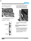
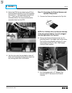
Step 12: Connecting the Sensor Harness and
the DTA Harness
A. Drill a .438" diameter hole in the left Breaker
Channel (See Drilling Plan B).
NOTE: Cover the Sensors before drilling
the holes.
Drilling Plan “B” – Front View