


Effective December, 1998
IL 33-K2C-1
Page 12
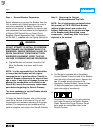
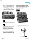
For Kits Supplied with a PT Module Only.
The Glass Poly Barrier must be mounted so
the PT Module will face the rear of the Trip
Unit when mounted.
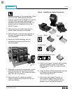
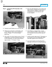
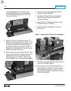
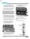
C. Mount the Trip Unit to the top of the Aux. CT
Module as shown using the (2) .190-32 × 4.00"
screws, (2) lock washers, (2) flat washers, and
(2) spacers supplied. Note that the spacers
are positioned between the top of the Aux. CT
Module and the bottom of the Trip Unit. Do not
tighten the screws at this time.
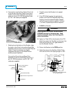
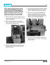
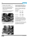
D. Mount the left and right Trip Unit Support Clips
to the sides of the Aux. CT Module and into the
bottom front slots in the Trip Unit as shown.
Secure using the (4) .190-32 × .375" screws,
(4) flat washers, and (4) lock washers supplied.
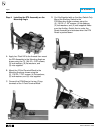
E. Secure the Trip Unit by tightening the 4.00"
screws installed in Step 8-B.
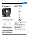
F. Remove the Trip Unit Cover and install the
Rating Plug supplied with the Retrofit Kit.
Reinstall the Cover.
G. Install the Aux. CT Harness between the Trip
Unit and the Aux. CT Module.
H. Install the Digitrip Nameplate on the top of
the Trip Unit.
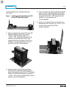
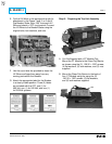
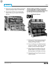
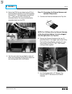
Step 9: Installing the Trip Unit on the Breaker
A. Remove and scrap the two (2) screws from the
right side of Breaker Platform.
B. Mount the right Trip Unit Mounting Bracket on
top of the Breaker Platform, flush with the end
of the Breaker using the (2) .190-18 × .500"
thread cutting screws, (2) lock washers, and (2)
flat washers supplied.