


Effective December, 1998
IL 33-K2C-1
Page 6
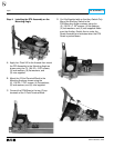
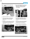
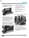
Step 4: Installing the DTA Assembly on the
Mounting Angle
A. Apply Loc-Tite
®
242 to the threads then mount
the DTA Assembly to the Mounting Angle as
shown using the (3) .164-32 × .500" screws,
(3) lock washers, (6) flat washers, and
(3) nuts supplied.
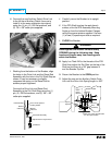
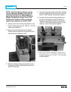
B. Mount the 2-Point Terminal Block to the
Mounting Angle as shown using the
(2) .138-32 × .750" screws, (4) flat washers,
(2) lock washers, and (2) nuts supplied.
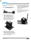
C. Connect the DTA Wires to the two (2) top
terminals of the 2-Point Terminal Block.
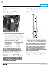
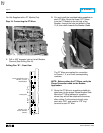
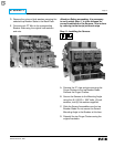
D.
For Kits Supplied with an Auxiliary Switch Only.
Mount the Auxiliary Switch to the
DTA Mounting Angle as shown using the
(2) .138-32 × 1.25" screws, (4) flat washers,
(2) lock washers, and (2) nuts supplied. Make
sure the Auxiliary Switch Arm is under the
Reset Assembly and activates when the DTA
Reset is pushed down.