


Effective December, 1998
IL 33-K2C-1
Page 16
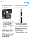
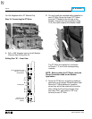
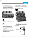
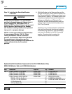
1.25"
0.56"
0.266" Dia. Holes
5.44"
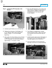
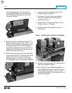
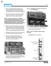
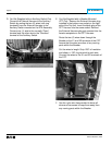
E. Mount the (2) threaded coupling nuts to the
top rear of the Breaker, using the (2)
.375-16 × .750" bolts, (2) flat washers, and
(2) lock washers supplied. Mount the Sensor
Mounting Angle to the threaded cap nuts, as
shown, using the (2) .375-16 × .750" bolts, (2)
flat washers, and (2) lock washers supplied.
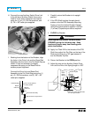
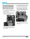
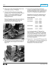
F.
Reinstall the bottom Finger Clusters (removed
in Step 2-B) using the original hardware.
Reinstall the original Fuses, Fuse mountings,
and associated hardware (removed in
Step 2-B) on the bottom Breaker Stabs.
Refer to the ITE K-1600 / 2000 Instruction
Manual, originally supplied with the Breaker
for more information.
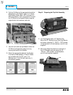
G. Rotate the Secondary Contact Bracket to its
original position (loosened in Step 2-A). Secure
it by reinstalling the original top screws and
tightening the bottom screws.
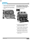
Attention: Before proceeding, it is necessary
to verify which Step 11 is to be followed for
correct installation of the Sensors. This is done
by referring to the Icon(s) with each step.
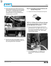
Step 11: Installing the Sensors
A. Drill two .266" diameter holes in each side of
the rear Breaker Frame (See Drilling Plan “C”).
Drilling Plan “C”