


Effective December, 1998
IL 33-K2C-1
Page 18
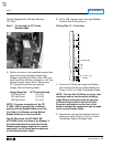
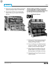
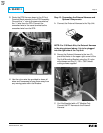
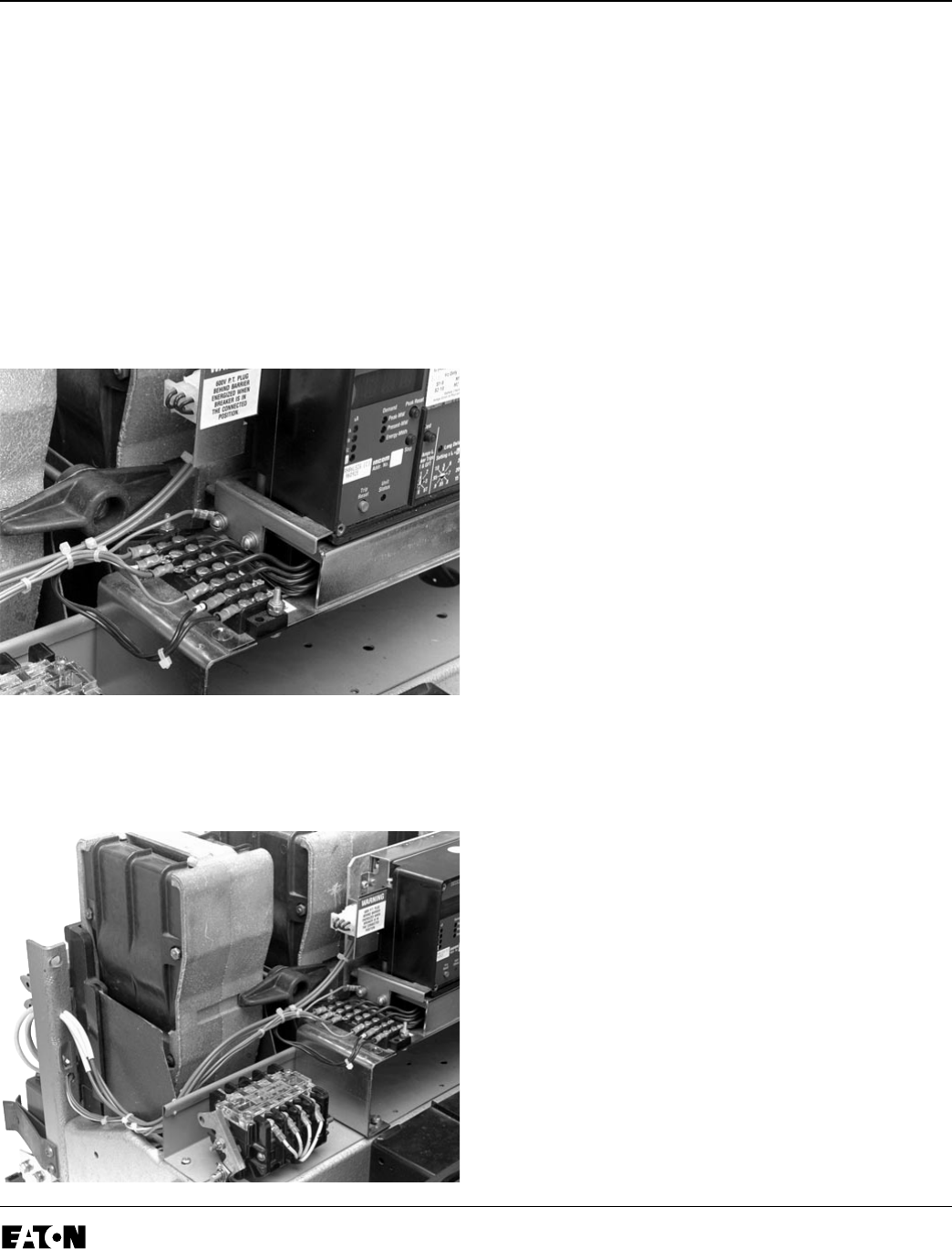
B. Remove the 7-Point Terminal Block Cover from
the left side of the Aux. CT Module.
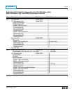
C. Connect the Sensor Harness to the proper
terminals of the 7-Point Terminal Block. Refer to
Section 12 of the Retrofit Application Data,
supplied with the Retrofit Kit, for detailed
wiring specifications.
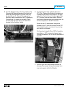
Connect the green ground wire from the Sensor
Harness (with the ring terminal) to the rear
screw of the left Trip Unit Support Clip.
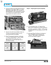
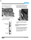
D. Route the Sensor Harness towards the left rear
of the Breaker, then through the hole drilled in
Step 12-A.
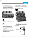
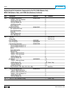
E. Connect the ring terminals of the Sensor
Harness to the Sensors. Refer to Section 12 of
the Retrofit Application Data, supplied with the
Retrofit Kit, for detailed wiring specifications.
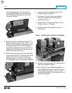
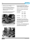
Depending on the Sensors supplied with the
Retrofit Kit, the following conventions apply.
Sensor Style No.
8187A55H01: X1-X2 = 200 A
8187A56H01: X1-X4 = 800 A
X1-X3 = 600 A
X1-X2 = 400 A
8187A57H01: X1-X4 = 1600 A
X1-X3 = 1200 A
8189A46H01: X1-X2 = 2000 A
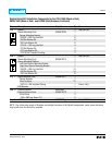
For Kits Supplied with a PT Module Only.
Refer to Section 7-3, Power Flow Convention
of the Retrofit Application Data, supplied with
the Retrofit kit for additional wiring information
and to verify the Phase Convention used on
this Breaker Application.
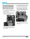
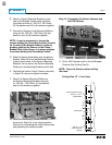
F. Connect the “+” wire of the DTA Harness to the
“OP” terminal of the 7-Point Terminal Block and
the unmarked wire to the “ON” terminal.
Reinstall the 7-Point Terminal Cover.