


Effective December, 1998
IL 33-K2C-1
Page 7
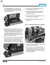
For Kits Supplied with a Breaker Mounted
CPT Only.
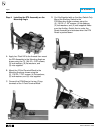
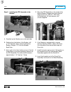
Step 5: Installing the Breaker Mounted CPT
on the DTA Mounting Angle
A. Mount the Breaker Mounted CPT to the CPT
Mounting Plate as shown using the (2)
.190-32 × .500" flat head screws, (2)
.190-32 × .500" filister head screws, (6) flat
washers, (4) lock washers, and (4) nuts
supplied. Note the orientation of the CPT to
the holes in the Mounting Plate. The CPT
must be mounted in this orientation.
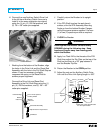
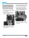
B.
Align the holes in the CPT Mounting Plate
with the holes in the DTA Mounting Angle as
shown. Secure the left side of the CPT Mounting
Plate to the DTA Mounting Angle using the (2)
.164-32 × .625" screws, (4) flat washers, (2) lock
washers, and (2) nuts supplied.
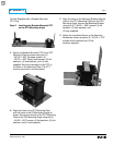
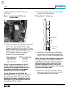
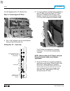
C. Align the holes in the Mounting Bracket with the
holes in the CPT Mounting Plate and the DTA
Mounting Angle. Secure the Mounting Bracket
using the (2) .164-32 × .625" screws, (4) flat
washers, (2) lock washers, and
(2) nuts supplied.
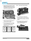
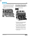
D. Attach the Insulation Barrier to the Mounting
Bracket as shown using the (2) .164-32 × .312"
screws w/lock washers and (2) flat
washers supplied.