


Effective December, 1998
IL 33-K2C-1
Page 5
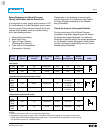
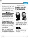
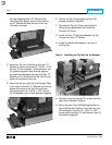
K-1600
K-2000 (Red)
KDON-1600 (Black and Red)
(Black)
(Red)
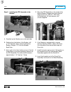
Note the orientation of the existing fuses. Follow
the ITE K-1600 / 2000 Instruction Manual,
originally supplied with the Breaker, and remove
the fuses, fuse mountings, and associated
hardware from the bottom Breaker Stabs. Set
all parts aside for reinstallation later in the
Retrofit Process.
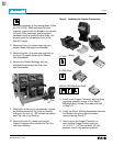
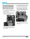
C. Remove the four (4) screws securing each
bottom Glastic Moldings to the Breaker.
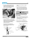
D. Remove the four (4) screws securing each of
the three (3) copper pieces to the Breaker
Pole Assemblies.
E. Remove the Glastic Moldings, with the
attached Electromechanical Trip Units,
from the Breaker.
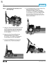
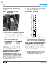
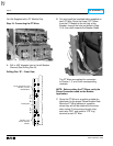
F. Working from the rear of the assembly, remove
the Electromechanical Trip Units by carefully
drilling out the four (4) .190" screws that secure
each Trip Unit to the Molding.
G. Remove the two (2) screws securing the
Copper Extensions then remove the Trip Unit
from each Molding.
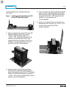
Step 3: Installing the Copper Connectors
A. Install a new Copper Connector, with the short
leg facing upwards, in each of the Glastic
Moldings using the two (2) screws removed
in Step 2-G.
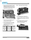
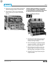
B. Install the Glastic Molding Assemblies back into
the Breaker using the original hardware
removed during Step 2-C.
C. Secure each new Copper Connector to
each existing Copper Contact using the
(4) .312-18 × 1.12" hex cap bolts, (4) lock
washers, and (4) flat washers supplied.