


3. Instruction Set
3-363
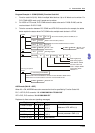
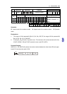
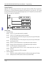
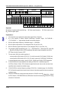
API Mnemonic Operands Function
156
D ZRN
Zero return
Controllers
ES2/EX2 SS2 SA2
SE
SX2
Bit Devices Word Devices Program Steps Type
OP
X Y M S K H KnX KnY KnM KnS T C D E F
S
1
* ** * * * * * * *
S
2
* ** * * * * * * *
S
3
*
D *
DZRN: 17 steps
PULSE 16-bit 32-bit
ES2/EX2 SS2
SA2
SE
SX2 ES2/EX2 SS2
SA2
SE
SX2 ES2/EX2 SS2
SA2
SE
SX2
Operands:
S
1
: Target frequency for zero return S
2
: JOG frequency for DOG S
3
: input device for DOG D:
Pulse output device
Explanations:
1. S
1
(zero return speed): max. 100kHz. S
2
(JOG speed for DOG) has to be lower than S
1.
JOG
speed for DOG also refers to the start frequency.
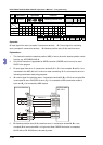
2. S
3
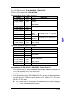
and D operands have to be used as an input/output set according to the table below, i.e. when
S
3
is specified as X4, D has to be specified as Y0; also when S
3
is specified as X6, D has to be
specified as Y2.
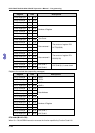
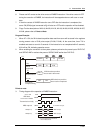
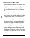
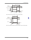
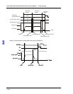
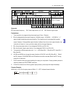
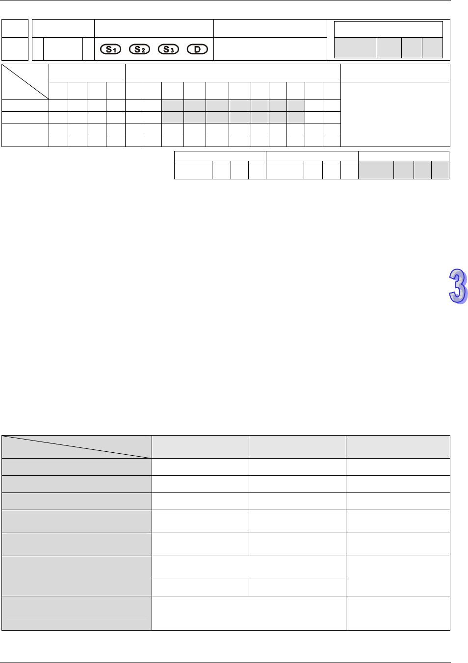
3. M1307 enables (ON) / disables (OFF) left limit switch of CH0 (Y0, Y1) and CH1 (Y2, Y3). M1307
has to be set up before the instruction executes. M1305 and M1306 can reverse the pulse output
direction on Y1 and Y3 and have to be set up before instruction executes. Associated left limit
switch for CH0 (Y0, Y1) is X5; associated left limit switch for CH1 (Y2, Y3) is X7. All functions,
input points and output points are arranged as follows:
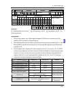
Channel
Input
CH0(Y0,Y1) CH1(Y2,Y3) Remark
DOG point X4 X6
Left limit switch (M1307 = ON) X5 X7
Reverse pulse output direction M1305 M1306
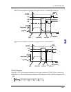
Zero point selection M1106 M1107
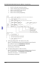
Please refer to point
7 for the explanation.
M1346=On
Start output clear signals
Y4 Y5
Please refer to point
8 for the explanation.
M1308 = Off
(seeking Z-phase signal)
D1312 != 0
X2 X3
Please refer to point
9 for the explanation.
D1312 != 0
M1308 = On
(outputting the designated number of
pulses)
Please refer to
point 10 for the
explanation.