3. Instruction Set
3-247
2. When control mode (S
3
+4) is selected as K3 and K4:
y The equation is exclusively for temperature control will be modified as:
() () ()
⎥
⎦
⎤
⎢
⎣
⎡
+
⎟
⎠
⎞
⎜
⎝
⎛
+= StEK
S
tE
K
tE
K
MV
D
IP
*
111
,
where
() () ()
tPV-tSVtE
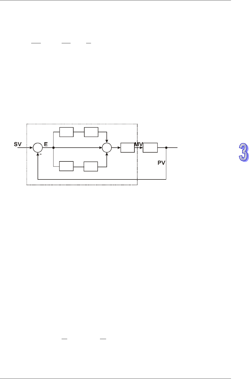
y Control diagram:
In diagram below, 1/K
I
and 1/K
P
refer to “divided by K
I
” and “divided by K
P
”. Because this mode
is exclusively for temperature control, users have to use PID instruction together with GPWM
instruction. See Application 3 for more details
G(s)
S
1/S
1/K
I
K
D
+
+
+
PID operation is within dotted area
P
+
1/K
y This equation is exclusively designed for temperature control. Therefore, when the
sampling time (T
S
) is set as 4 seconds (K400), the range of output value (MV) will be K0 ~
K4,000 and the cycle time of GPWM instruction used together has to be set as 4 seconds
(K4000) as well.
y If users have no idea on parameter adjustment, select K3 (auto-tuning). After all the
parameters are adjusted (the control direction will be automatically set as K4), users can
modify the parameters to better ones according to the adjusted results.
3. When control mode (S
3
+4) is selected as K10:
y S
3
+2 (K
I
) and S
3
+3 (K
D
) in this mode will be switched to parameter settings of Integral
time constant (T
I
) and Derivative time constant (T
D
).
y When output value (MV) reaches the upper bound, the accumulated integral value will
not increase. Also, when MV reaches the lower bound, the accumulated integral value will not
decrease.
y The equation for this mode will be modified as:
() () ()
⎥
⎦
⎤
⎢
⎣
⎡
++×=
∫
tE
dt
d
TdttE
T
tEKMV
D
I
P
1


