3. Instruction Set
3-179
The conversion will be performed in the following rule:
‘1’
‘2’
‘3’
Hi-byte Lo-byte
‘.’
D+0
D+1
D+2
D+3
‘4’
‘5’
‘6’
0x00
D+4
D+5
D+6
D+7
123.45678
32-bit Floating value
S+0
S+1
n = k6
‘1’
‘2’
‘3’
Hi-byte Lo-byte
‘.’
D+0
D+1
D+2
D+3
‘4’
‘5’
‘6’
0x00
D+4
D+5
D+6
D+7
123.45678
32-bit Floating value
S+0
S+1
n = k6
Program Example 1: K2, K4
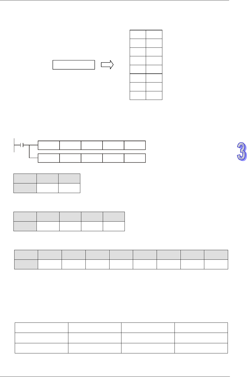
1. When M0 = ON, transform 16-bit data in D0, D1 into ASCII data in the following order: H byte -
L byte - H byte - Low byte, and store the results in D10 ~ D17.
M0
DTM D0 D2 K2
K2
DTM D2 D10 K4
K4
2. Value of source devices D0, D1:
Register D0 D1
Value H1234 H5678
3. When the 1
st
DTM instruction executes (m=K2), ELC transforms the 16-bit data (Hi-byte,
Lo-byte) into 8-bit data and move to registers D2~D5.
Register D2 D3 D4 D5
Value H12 H34 H56 H78
4. When the 2
nd
DTM instruction executes (m=K4), ELC transforms the 8-bit HEX data into ASCII
data and move to registers D10~D17.
Register D10 D11 D12 D13 D14 D15 D16 D17
Value H0031 H0032 H0033 H0034 H0035 H0036 H0037 H0038
Program Example 2: K9
151. Set up total number of pulses, total time, ramp-up time and ramp-down time in source device
starting with D0. Execute DTM instruction and the optimal max frequency as well as optimal
start frequency can be obtained and executed by positioning instructions.
152. Assume the data of source device is set up as below:
Total Pulses
Total Time Ramp-up Time
Ramp-down Time
D0, D1
D2 D3
D4
K10000
K200 K50
K50


