


3. Instruction Set
3-345
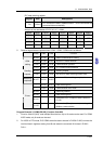
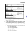
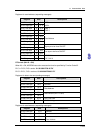
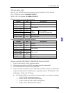
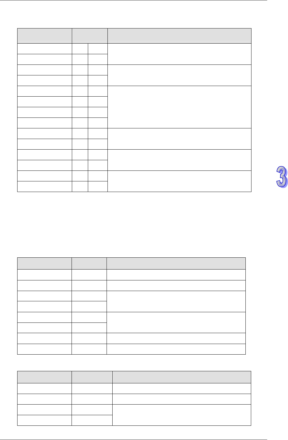
Registers for received data (responding messages)
Register Data Descriptions
D1070 low byte ‘0’ 30 H ADR 1
D1070 high byte ‘1’ 31 H ADR 0
D1071 low byte ‘0’ 30 H CMD 1
D1071 high byte ‘5’ 35H CMD 0
D1072 low byte ‘0’ 30 H
D1072 high byte ‘5’ 35 H
D1073 low byte ‘0’ 30 H
D1073 high byte ‘0’ 30 H
Data Address
D1074 low byte ‘F’ 46 H
D1074 high byte ‘F’ 46 H
High byte to be force ON/OFF
D1075 low byte ‘0’ 30H
D1075 high byte ‘0’ 30 H
Low byte to be force ON/OFF
D1076 low byte ‘6’ 36 H LRC CHK 1
D1076 high byte ‘F’ 46 H LRC CHK 0
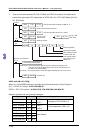
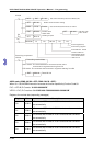
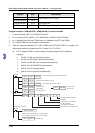
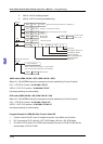
RTU mode (M1143 = ON)
When X0 = ON, MODRW instruction executes the function specified by Function Code 05
PLC1Ö PLC2, PLC1 sends: “01 05 0500 FF00 8C F6”
PLC2 ÖPLC1, PLC1 receives: “01 05 0500 FF00 8C F6”
Registers for data to be sent (sending messages)
Register Data Descriptions
D1256 Low byte 01 H Address
D1257 Low byte 05 H Function
D1258 Low byte 05 H
D1259 Low byte 00 H
Data Address
D1260 Low byte FF H
D1261 Low byte 00 H
Data content (ON = FF00H)
D1262 Low byte 8C H CRC CHK Low
D1263 Low byte F6 H CRC CHK High
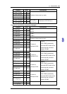
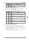
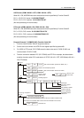
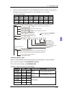
Registers for received data (responding messages)
Register Data Descriptions
D1070 Low byte 01 H Address
D1071 Low byte 05 H Function
D1072 Low byte 05 H
D1073 Low byte 00 H
Data Address