


3. Instruction Set
3-337
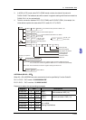
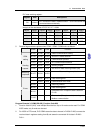
PLC data receiving register:
Register Data Descriptions
D0 1234 H
PLC converts the data in address 0500H ~ 0515H and stores the
converted data automatically.
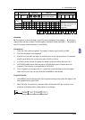
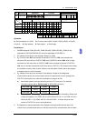
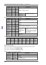
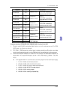
Analysis of the read status of PLC2 Y0~Y17: 1234H
Device Status Device Status Device Status Device Status
Y0 OFF Y1 OFF Y2 ON Y3
OFF
Y4 ON Y5 ON Y6
OFF
Y7
OFF
Y10 OFF Y11 On Y12
OFF
Y13
OFF
Y14 ON Y15 OFF Y16
OFF
Y17
OFF
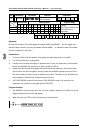
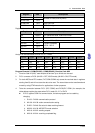
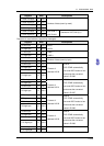
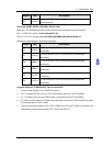
5. Relative flags and data registers when COM1 / COM2 / COM3 works as Master:
COM2 COM1 COM3 Function
M1120 M1138 M1136
Retain communication setting
M1143 M1139 M1320
ASCII/RTU mode selection
D1120 D1036 D1109 Communication protocol
COM.
setting
D1121 D1121 D1255 PLC communication address
M1122 M1312 M1316
Sending request
Sending
request
D1129 D1249 D1252 Set value for data receiving timeout (ms)
Receiving
completed
M1127 M1314 M1318
Data receiving completed
- M1315 M1319 Data receiving error
- D1250 D1253 Communication error code
M1129 - - Receiving timeout
M1140 - - Data receiving error
M1141 - -
Parameter error. Exception Code is stored in
D1130
Errors
D1130 - -
Error code (Exception code) returning from
Modbus communication
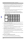
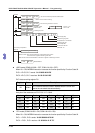
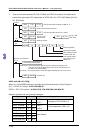
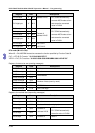
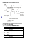
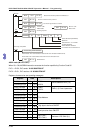
Program Example 3: COM2 (RS-485), Function Code H03
1. Function code K3 (H03): read multiple Word devices. Up to 16 words can be read. For COM2
ASCII mode, only 8 words can be read.
2. For ASCII or RTU mode, PLC COM2 stores the data to be sent in D1256~D1295, converts the
received data in registers starting from S, and stores the converted 16-bit data in D1296 ~
D1311.