


A-9
Cisco VG224 Voice Gateway Hardware Installation Guide
OL-5006-04
Appendix A Cable Specifications and Information
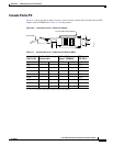
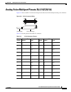
Analog Voice Multiport Pinouts (RJ-21X/CA21A)
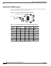
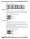
V.35 Connections
The V.35 standard is recommended for speeds up to 48 kbps, although in practice it is used successfully
at 4 Mbps. The Cisco VG224 voice gateway supports speeds up to 2.048
Mbps.
Use the V.35 serial transition cable (not included) with the Cisco 12-in-1 connector on one end and a
standard 34-pin Winchester-type connector (as shown in
Figure A-9) on the other. The 34-pin
Winchester-type connector can be male for DTE or female for DCE. To order a cable, see the “Obtaining
Technical Assistance” section on page 16.
Figure A-9 V.35 Serial Transition Cable Connectors
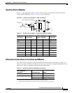
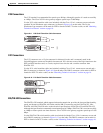
X.21 Connections
The X.21 connector uses a 15-pin connector for balanced circuits and is commonly used in the
United
Kingdom to connect to the public data network. X.21 relocates some of the logic functions to the
DTE and DCE interfaces and, as a result, requires fewer circuits and a smaller connector than
EIA/TIA-232.
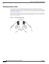
Use the X.21 serial transition cable (not included) with the Cisco 12-in-1 connector on one end and a
DB-15 connector (as shown in
Figure A-10) on the other. The DB-15 connector can be male for DTE or
female for DCE. To order a cable, see the “Obtaining Technical Assistance” section on page 16.
Figure A-10 X.21 Serial Transition Cable Connectors
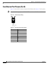
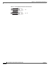
EIA/TIA-530 Connections
The EIA/TIA-530 standard, which supports balanced transmission, provides the increased functionality,
speed, and distance of EIA/TIA-449 on the smaller, DB-25 connector used for EIA/TIA-232. Like
EIA/TIA-449, EIA/TIA-530 refers to the electrical specifications of EIA/TIA-422 and EIA/TIA-423.
Although the specification recommends a maximum speed of 2 Mbps, EIA/TIA-530 is used successfully
at 4 Mbps or faster speeds over short distances. Cisco
VG224 voice gateway supports speeds up to 2.048
Mbps.
Use the EIA/TIA-530 serial transition cable (not included) with the Cisco 12-in-1 connector on one end
and a DB-25 connector (as shown in
Figure A-11) on the other. The DB-25 connector can be male for
DTE or female for DCE. To order a cable, see the “Obtaining Technical Assistance” section on page 16.
1
8
15
9
DCE
DTE
194833
194834
DTE
DCE