


3-16
Cisco VG224 Voice Gateway Hardware Installation Guide
OL-5006-04
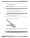
Chapter 3 Installing the Cisco VG224 Voice Gateway
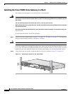
Connecting Cables
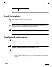
Connecting the Input Power
Caution
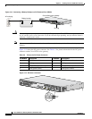
The Cisco VG224 voice gateway chassis provides inputs for both AC and DC power. Design your
installation to use only one type of power. Do not use AC and DC power at the same time. If you do, the
unit stops operating, and you need to reboot it with only a single power source.
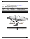
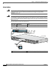
Cable
Use the AC power cable.
Procedure
Step 1
Connect the AC power cable (supplied) to the recessed power plug on the rear of the concentrator.
Step 2
Plug the cable into a power source with a voltage of 100 to 240 VAC.
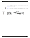
Connecting the Console Port to a PC or an ASCII Terminal
Use the procedure in this section to connect the console port to a PC running terminal emulation
software.
Note
The console port does not support hardware flow control.
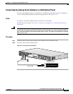
Cable
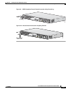
Use an RJ-45-to-RJ-DB-9 console cable (see item 5 in Figure 3-11 on page 3-15)
For pinouts, see Table A-1 on page A-3 and Table A-2 on page A-4 in Appendix A, “Cable
Specifications and Information.”
Procedure
Step 1
Configure the terminal emulation software requirements:
9600 baud
8 data bits
1 stop bit
no parity
no flow control