


3-21
Cisco VG224 Voice Gateway Hardware Installation Guide
OL-5006-04
Chapter 3 Installing the Cisco VG224 Voice Gateway
Connecting Backup Power
Connecting to a Remote ASCII Terminal
To link a Cisco VG224 voice gateway to a remote ASCII terminal, such as a VT100, use the following
procedure:
Step 1
Connect the remote ASCII terminal and modem.
Step 2
Set the terminal requirements:
9600 baud
8 data bits
1 stop bit
no parity
no flow control.
Step 3
Key in the telephone number of the Cisco VG224 voice gateway external modem, or, if you are using a
Hayes-compatible modem, enter ATDT and the number to be dialed.
Connecting Backup Power
A Cisco VG224 voice gateway can be installed with optional backup power. Backup power to a
DC-powered chassis is provided by a 12-volt battery backup system; see the
“Connecting a Backup
Battery to a DC-Powered Cisco VG224” section for connection instructions. Backup power to an
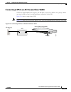
AC-powered chassis is provided by an uninterruptible power supply (UPS); see the “Connecting a UPS
to an AC-Powered Cisco VG224” section for connection instructions.
Caution
The Cisco VG224 chassis provides inputs for both AC and DC power. Design your installation to use
only one type of power. Do not use AC and DC power at the same time. If you do, the unit stops
operating, and you must reboot it with only a single power source.
The maximum power requirement for the Cisco VG224 voice gateway is 70 W.
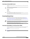
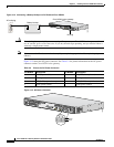
Connecting a Backup Battery to a DC-Powered Cisco VG224
Connect a 12-volt backup battery to the DC input connector on your Cisco VG224 voice gateway. Before
you install a backup battery, be sure to read the installation instructions for the backup battery
equipment.
Figure 3-14 shows a setup using an external backup battery.
Note
Figure 3-14 shows one possible setup; please review your backup battery documents before setting up
your system.