


A-1
Cisco VG224 Voice Gateway Hardware Installation Guide
OL-5006-04
APPENDIX
A
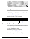
Cable Specifications and Information
This appendix provides the connector and pinout information you need for making or purchasing cables
used with Cisco
VG224 voice gateway. To order cables from Cisco, see the “Obtaining Technical
Assistance” section on page 16. This appendix contains the following sections:
•
Console and Auxiliary Port Cables and Pinouts, page A-1
•
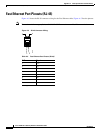
Fast Ethernet Port Pinouts (RJ-45), page A-6
•
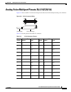
Analog Voice Multiport Pinouts (RJ-21X/CA21A), page A-7
The following list shows you which table to see for pinout information:
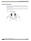
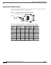
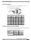
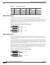
Console and Auxiliary Port Cables and Pinouts
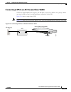
Your Cisco VG224 voice gateway comes with the cable and adapters you need to connect a PC, an ASCII
terminal, or a modem to your Cisco VG224 voice gateway. The cable kit includes:
•
RJ-45-to-RJ-45 rollover cable
•
RJ-45-to-DB-9 adapter cable for console connection
•
RJ-45-to-DB-25 adapter cable for modem connection
The following illustrations and tables provide cable pinout information:
•
Console port to a PC—See Table A-1 and Table A-4
•
Console port to an ASCII terminal—See Table A-2 and Table A-4
•
Auxiliary port to a modem—See Table A-3 and Table A-4
The console port is configured as data communications equipment (DCE); the auxiliary port is
configured as data terminal equipment (DTE). Both are asynchronous serial ports and use RJ-45
connectors.
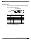
Cisco VG224 Voice Gateway Port and Connection Type Pinout Information
Console Port to PC—Cable Pinouts (RJ-45 to DB-9) Table A-1 on page A-3
Console Port to ASCII Terminal—Cable Pinouts (RJ-45 to DB-25) Table A-2 on page A-4
Auxiliary Port to Modem—Cable Pinouts (RJ-45 to DB-25) Table A-3 on page A-5
Alternative Terminal and Modem Connections Table A-4 on page A-5
Fast Ethernet Port Pinouts (RJ-45) Table A-5 on page A-6