


1-6
Cisco VG224 Voice Gateway Hardware Installation Guide
OL-5006-04
Chapter 1 Overview of the Cisco VG224 Voice Gateway
Chassis Grounding
Chassis Grounding
Chassis grounding is provided through the power cable, which uses a standard grounding plug. The
chassis is also equipped with two multi 4 x 0.7 screw terminals for chassis grounding. The accessory kit
contains a crimp-type ground lug that attaches to the two screw terminals. For more information, refer
to the
“Installing the Ground Connection” section on page 3-11.
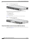
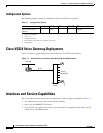
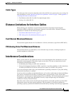
Port Numbering Conventions
Port numbering conventions for the Cisco VG224 are as follows:
•
An external compact flash card is numbered CF 0.
•
10/100BASE-T ports are numbered 10/100BASE-T 0/0 and 10/100BASE-T 0/1 from right to left.
•
FXS voice port numbering begins at 2/0 and extends to 2/7, 2/15, or 2/23, depending on the number
of voice ports.
Specifications
Ta b l e 1-3 Cisco VG224 Voice Gateway Technical Specifications
Characteristic Value
Dimensions 1.75H x 17.5W x 13.5D in. (44.4 x 444.5 x 342.9 mm)
Weight 11 lb (4.106 kg) max
Input power 100 to 240 VAC, 1 A (max), 50 to 60 Hz, 70 W (max)
Maximum power surge
Input power
(DC 12 volt battery) by chassis
60 W (204.7 BTU/h)
Caution
Do not try to use AC and DC power at the same time. If you do, the unit stops
operating and you have to reboot using a single power source.
MTBF 195,671 hours
Operating environment 32 to 122° F (0 to 50° C)
Nonoperating temperature –40 to 185° F (–40 to 85° C)
Operating humidity 5 to 95%, noncondensing
Noise level 55 dB @ 3 ft
Agency approvals Refer to the Cisco VG224 Regulatory Compliance and Safety Information document at the
following URL:
http://www.cisco.com/en/US/products/hw/gatecont/ps2250/products_regulatory_approvals_a
nd_compliance_list.html