


A-4
Cisco VG224 Voice Gateway Hardware Installation Guide
OL-5006-04
Appendix A Cable Specifications and Information
Console and Auxiliary Port Cables and Pinouts
Console Port to ASCII Terminal
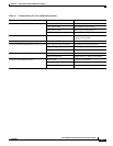
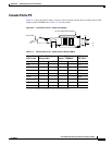
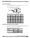
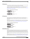
Figure A-3 shows the RJ-45-to-RJ-45 rollover cable assembly and the RJ-45-to-DB-25 female DTE
adapter (labeled TERMINAL); Table A-2 lists the pinouts.
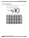
Figure A-3 Console Port to ASCII Terminal—Cable and Adapter
Ta b l e A-2 Console Port to ASCII Terminal—Cable Pinouts (RJ-45 to DB-25)
Console Port
(DCE, RJ-45)
RJ-45-to-RJ-45
Rollover Cable
RJ-45-to-DB-25
Adapter “TERMINAL”
Terminal Port
(DTE, DB-25)
Signal RJ-45 Pin RJ-45 Pin RJ-45 Pin DB-25 Pin Signal
RTS 1
1
1. Pin 1 is connected to pin 8 inside the Cisco VG224 voice gateway.
8 8 5 CTS
DTR 2 7 7 6 DSR
TxD 3 6 6 3 RxD
GND 4 5 5 7 GND
GND 5 4 4 7 GND
RxD 6 3 3 2 TxD
DSR 7 2 2 20 DTR
CTS 8
1
1 1 4 RTS
TERMINAL
CAB-500DTF
13
RJ-45 cable
8
1
RJ-45-to-DB-25 female adapter
H11193
1
14
25