


1-5
Cisco VG224 Voice Gateway Hardware Installation Guide
OL-5006-04
Chapter 1 Overview of the Cisco VG224 Voice Gateway
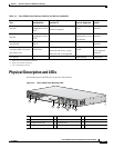
Physical Description and LEDs
Physical Description and LEDs
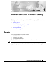
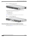
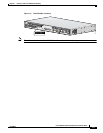
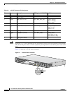
All interface ports and LEDs are on the rear of the chassis.
Figure 1-5 Cisco VG224 Voice Gateway LEDs
Ta b l e 1-2 Cisco VG224 Voice Gateway Interfaces and Service Capabilities
Port
Interface
Configurations
Interface To Services Supported Details
Console
Port 0/0
EIA/TIA-232
asynchronous serial
(DCE
1
)
1. DCE = data communications equipment
ASCII terminal
Personal computer
Local administrative
access
RJ-45 physical
interface
Auxiliary
Port 0/1
EIA/TIA-232
asynchronous serial
(DTE
2
)
2. DTE = data terminal equipment
Modem Remote
administrative access
Data backup
RJ-45 physical
interface
Fast Ethernet
Port 0/0, 0/1
10/100BASE-T
(802.3)
LAN Data RJ-45 physical
interface
RJ-21
24 analog FXS voice ports
Port 2/0 to 2/23
FXS (loop-start or
ground-start)
Analog phone, fax, or modem
Network side of key system
Network side of analog PBX
Analog voice/fax or
modem
Provides battery
RJ-21 physical
interface
CF
3
Slot 0
3. CF = compact flash memory
Flash memory Flash card
1 Chassis ground connection 5 Fast Ethernet port 0 9 On/off switch
2 RJ-21 connector 6 AUX port 10 AC power input
3 Compact flash port 7 Console port
4 Fast Ethernet port 1 8 DC power input
1
1. This is not a redundant failover power supply connection. You must use either DC or AC.
95914
2
4
5
6
7
8
9
10
3
1
VG224-24FXS