


3-20
Cisco VG224 Voice Gateway Hardware Installation Guide
OL-5006-04
Chapter 3 Installing the Cisco VG224 Voice Gateway
Ports, Connectors, and Pinouts
Ports, Connectors, and Pinouts
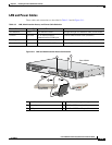
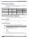
Table 3-4 summarizes the cable connections between Cisco VG224 voice gateway and the network and
user interfaces. Find the port and the equipment or network type in the table; then look at the applicable
pinout table in
Appendix A, “Cable Specifications and Information.”
Remote Terminal Connections (If Applicable)
If you are configuring a Cisco VG224 voice gateway from a remote location, connect the modem and
the remote PC or terminal to the telephone network as described in this section.
Connecting to a Modem
To connect the local modem and the remote modem to live telephone outlets, use standard telephone
cables.
Connecting to a Remote PC
To link a Cisco VG224 voice gateway to a remote PC, use the following procedure:
Note
The remote PC must be running terminal emulation software.
Step 1
Connect the remote PC and modem.
Step 2
Set the PC terminal emulation software requirements:
9600 baud
8 data bits
1 stop bit
no parity
no flow control.
Step 3
Key in and dial the telephone number of the Cisco VG224 voice gateway external modem.
Ta b l e 3-4 Cable Use Reference Table
Cisco VG224 Port Port Color Connector/Cable Interface To Pinout Information
Console Light blue RJ-45/Rollover PC Table A-1
ASCII terminal Table A-2
Auxiliary Black RJ-45/Rollover Modem Table A-3
Fast Ethernet Yellow RJ-45/Fast Ethernet LAN Table A-5
Analog voice multiport Gray RJ-21X/
50-conductor
Distribution panel for analog
telephone, fax, PBX, or
central office line
Table A-6