


3-15
Cisco VG224 Voice Gateway Hardware Installation Guide
OL-5006-04
Chapter 3 Installing the Cisco VG224 Voice Gateway
Connecting Cables
LAN and Power Cables
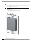
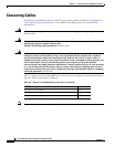
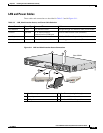
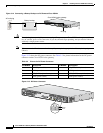
These cables and connections are described in Table 3-3 and in Figure 3-11.
Figure 3-11 LAN and Administrative Access Connections
Ta b l e 3-3 LAN, Administrative Access, and Power Cable Selection
Port or Connection Color or Type Connected To Cable
Fast Ethernet Yellow Fast Ethernet switch Straight-through Fast Ethernet cable (not included)
Console Light blue PC or ASCII terminal
communication (COM) port
RJ-45-to-DB9 console cable (included)
Auxiliary Black Modem for remote access RJ-45-to-DB25 auxiliary cable (included)
Power (not shown) Power 100–240 VAC, 50–60 Hz Grounding power cord (included)
1
1. Power cables vary to meet local requirements.
1 Fast Ethernet port 4 Fast Ethernet (straight-through)
2 Console port 5 RJ-45-to-DB9 console cable
3 AUX port 6 RJ-45-to-DB25 auxiliary cable
95920
VG224-24FXS
4
5
6
Ethernet hub
1
2
3
Cisco VG224
Modem
PC