


3-12
Cisco VG224 Voice Gateway Hardware Installation Guide
OL-5006-04
Chapter 3 Installing the Cisco VG224 Voice Gateway
Installing the Ground Connection
•
For EN/IEC 60950-compliant grounding, use size AWG 18 (1 mm
2
) or larger wire and an
appropriate user-supplied ring terminal.
To ground the chassis, follow this procedure:
Step 1
Locate a suitable ground location.
Tip
Use a multimeter to measure the resistance between various ground locations, such as the following:
•
Between the ground of a junction box (outlet) and the ground of a power tap
•
Between the ground of a junction box and a metal water pipe
•
Between the Cisco VG224 voice gateway chassis and the ground of a power tap
•
Between the Cisco VG224 voice gateway chassis and the ground of a junction box
A good ground connection should read between 0.0 and 0.5 ohms.
Step 2
Strip one end of the ground wire to the length required for the ground lug or terminal.
•
For the NEBS ground lug—approximately 0.75 in. (20 mm)
•
For user-provided ring terminal—as required
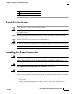
Step 3
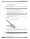
Crimp the ground wire to the ground lug or ring terminal, using a crimp tool of the appropriate size. (See
Figure 3-8.)
Figure 3-8 Crimping a Ground Lug onto the Ground Wire
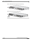
Step 4
Attach the ground lug or ring terminal to the chassis as shown in Figure 3-9 or Figure 3-10. For the
ground lug, use the two screws with captive locking washers provided. For a ring terminal, use one of
the screws provided. Use a number
2 Phillips screwdriver, and tighten the screws to a torque of 8 to 10
in-lb (0.9 to 1.1 N-m).
Note
You can orient the crimped end of the ground lug in either direction (right or left).
Step 5
Connect the other end of the ground wire to a grounding point at your site.
10360