


3-17
Cisco VG224 Voice Gateway Hardware Installation Guide
OL-5006-04
Chapter 3 Installing the Cisco VG224 Voice Gateway
Connecting Cables
Connecting the Auxiliary Port to a Modem
Use the procedure in this section to connect the auxiliary port to a modem.
Cable
Use an RJ-45-to-DB25 auxiliary cable (labeled Modem).
For pinouts, see Table A-3 on page A-5 and Table A-4 on page A-5 in Appendix A, “Cable
Specifications and Information.”
Procedure
Step 1
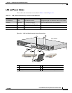
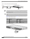
Connect the cable from the auxiliary port (black) to the DB-25 port on the modem. (See item 6 in
Figure 3-11 on page 3-15.)
Step 2
Configure the modem.
a.
Match the transmission speed of the auxiliary port (default is 9600 baud).
b.
Set the hardware flow control for Data Carrier Detect (DCD) and Data Terminal Ready (DTR)
operation.
Note
The baud rate for the auxiliary (and console) port can be configured in software for 1200, 2400, 4800,
19200, 38400, 57600, and 115200.
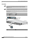
Connecting the Fast Ethernet Port to the Fast Ethernet Switch
Use the procedure in this section to connect a Fast Ethernet port to the Fast Ethernet switch.
Cable
Use a straight-through Fast Ethernet cable (not included).
Procedure
Step 1
Connect the cable from a Fast Ethernet port to an available port on the Fast Ethernet switch. (See item
4 in
Figure 3-11 on page 3-15.)
Step 2
Connect the second cable if it is required.
Note
Not all models have two ports.