


2-4
Cisco VG224 Voice Gateway Hardware Installation Guide
OL-5006-04
Chapter 2 Planning Your Installation
Location and Mounting Requirements
Caution
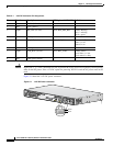
Signal pins 1, 3, 5, and 7 should be tied low to prevent the Cisco VG224 voice gateway from reporting
faults on the DC power. If the +12V DC option for powering VG224 is used the AC power must not be
used.
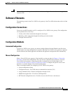
Figure 2-1 shows the +12V DC power connector.
Figure 2-1 +12V DC Power Connector
Ta b l e 2-1 +12V DC Connector Pin Assignment
Pin Direction Description SW Register 0x4A80_0038 Definition
1 Input Enable (tie low) — —
2 Input +12V (power) — —
3 Output REP_BAT (tie low) Bit 6: REP_MIS_BAT Battery Missing:
Fail 1 = missing
Fail 0 = good
4 Input GND (power return) — —
5 Output ON_BAT (tie low) Bit 4: BAT_ON Battery on/off:
Status 1 = off
Status 0 = on
6 Input +12V (power) — —
7 Output LOW_BAT (tie low) Bit 5: BAT_LOW Battery power:
Level status 1 = low
Level status 0 = okay
8 Input GND (power return) — —
103121
VG224-24FXS
Pin 1
Pin 5